


Universal Chromatography Interfaces
UCI-50 and UCI-100
Page
28
Operating Instructions
3.3.5.2 Configuring the UCI
Verify that the default settings are correct and change them if needed. If you want to change
the settings at a later date, double-click the UCI to reopen the configuration pages.
Tip:
Changing the settings for a specific application in the
Commands
dialog box,
in a program file (PGM), or on a control panel will not change the default
settings on the configuration pages.
For additional information about a page, click
Help
.
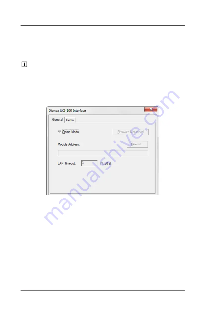
General page
The General page shows the general instrument parameters.
Fig. 13: General page
•
Demo Mode
Select the
Demo Mode
check box if you want to read and display a demo chromatogram
instead of real data. To specify the demo chromatogram, select the
Demo
tab
(
→
page 30).
•
Firmware Download
Click this button to transfer the firmware version available for the UCI in Chromeleon to
the module. (The button appears dimmed if the Demo Mode is enabled.)
The UCI is shipped with the most recent firmware version. If a firmware update is ever
required, follow the steps in section 5.2 (
→
page 43).
Summary of Contents for UCI-100
Page 2: ...Universal Chromatography Interfaces UCI 50 and UCI 100 Operating Instructions...
Page 4: ...Universal Chromatography Interfaces UCI 50 and UCI 100 Page II Operating Instructions...
Page 10: ...Universal Chromatography Interfaces UCI 50 and UCI 100 Page 4 Operating Instructions...
Page 48: ...Universal Chromatography Interfaces UCI 50 and UCI 100 Page 42 Operating Instructions...
Page 52: ...Universal Chromatography Interfaces UCI 50 and UCI 100 Page 46 Operating Instructions...
Page 54: ...Universal Chromatography Interfaces UCI 50 and UCI 100 Page 48 Operating Instructions...
Page 60: ...Universal Chromatography Interfaces UCI 50 and UCI 100 Page 54 Operating Instructions...


