background image


Symbol Indication 


Alternating current 


Earth terminal or ground 


Protective conductor terminal 

Fuse 


Power on 


Power off 


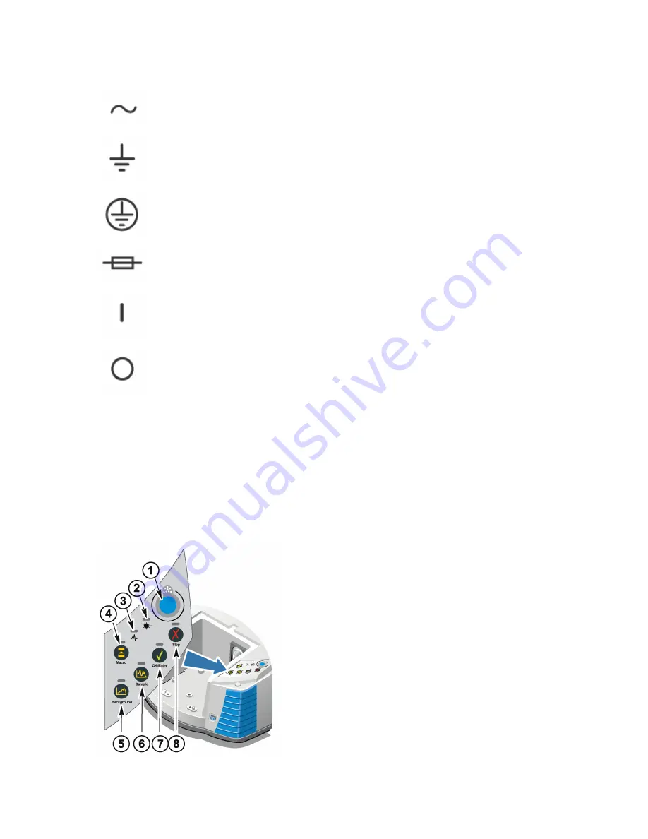
Indicators and buttons 

 
The status indicators for the instrument are located on the operations panel, which is on the 

main cover of the instrument. This panel also has buttons that allow you to operate the 

instrument. 


1)  Humidity indicator 


2)  Power indicator 


3)  Scan indicator 


4)  Macro button 


5)  Background button 


6)  Sample button 


7)  OK/Enter button 


8)  Stop button 

6        Using Your Nicolet iZ10 Module 

Thermo Fisher Scientific 

Summary of Contents for Nicolet iZ10

Page 1: ...Nicolet Series FT IR Spectrometers Nicolet iZ10 User Guide 269 233900 Revision B November 2018...

Page 2: ...s only System configurations and specifications in this document supersede all previous information received by the purchaser Thermo Fisher Scientific Inc makes no representations that this document i...

Page 3: ...ntaining your instrument 18 Cleaning your instrument 18 Static electricity precautions 18 Maintaining detector dewars 19 Checking the humidity indicator 19 Replacing the humidity indicator 20 Replacin...

Page 4: ...The MCT detector is warm 32 The laser voltage is out of specification 33 The source voltage is out of specification 33 The power supply voltages are out of tolerance 33 Index 34...

Page 5: ...here is a Find tab that allows you to search for specific words Questions and concerns In case of emergency follow the procedures established by your facility If you have questions or concerns about s...

Page 6: ...ner The system warranty period for products sold outside the U S A and Canada is 12 months from the date of installation or 14 months from the date of shipment whichever is sooner Limit of warranty Mi...

Page 7: ...e software is installed To access these PDFs 1 Click the Start button on the Windows taskbar 2 Click All Programs 3 Click the Thermo Scientific OMNIC folder 4 Click the Documentation folder 5 Choose t...

Page 8: ...ergy and high voltage may result Warning Never stare directly into the laser beam or at its bright reflection Avoid skin contact with the laser beam or its bright reflection Never tamper with the lase...

Page 9: ...s that shall not be taken or shall be stopped White graphical symbol inside a blue circle This is a mandatory action symbol It is used to indicate that an action shall be taken to avoid a hazard Black...

Page 10: ...r the instrument are located on the operations panel which is on the main cover of the instrument This panel also has buttons that allow you to operate the instrument 1 Humidity indicator 2 Power indi...

Page 11: ...itrogen make sure any dewar or container you use to hold liquid nitrogen can do so safely without breaking Using corrosives and solvents Caustic or corrosive agents Instrument components may be degrad...

Page 12: ...d hydrofluoric acid and phosgene are highly toxic If you regularly use solvents containing halogenated hydrocarbons your work area must be properly ventilated and your system must be purged while the...

Page 13: ...lable through the Help menu in OMNIC or the printed documentation that came with the system microscope or spectrometer Setting the purge gas controls You must connect a source of purge gas dry air or...

Page 14: ...re is between 0 7 and 1 4 bar 70 to 140 kPa or 10 to 20 psig Notice Flow rates greater than 10 scfh can cause vibration that can affect data quality We recommend keeping the flow rate at approximately...

Page 15: ...rogen is extremely cold and can be hazardous When you use liquid nitrogen always follow standard laboratory safety practices and make sure your dewar is made to use with liquid nitrogen Wear protectiv...

Page 16: ...unt of liquid nitrogen typically spills out of the funnel This will not harm your instrument Fill the funnel and then let it drain completely two or three times Wait until the vapor plume disappears a...

Page 17: ...ing Pipe tape Note To order parts contact us Note For best results the purge gas should be dried to a dew point of 70 degrees C 94 degrees F or below Warning Never use a flammable gas to purge your in...

Page 18: ...d wrench to tighten the connection 4 Install the purge filter pressure regulator and flowmeter and then snap the assembly into the pressure coupling 5 Connect the purge kit to your instrument set the...

Page 19: ...save it with its cap and screw in a safe place in case you want to reinstall it later 3 Place the sample compartment extension on the front of the sample compartment Make sure the pins in the same com...

Page 20: ...dure applies only if a sample compartment expansion kit has been installed Notice Your accessory must be mounted on one of our baseplates If it is not you can remove an accessory from one of our basep...

Page 21: ...he sidewall to compress the purge gasket and then slide the adapter down into the clips on the side of the transmission sample compartment Note To remove a sidewall adapter press the adapter ring towa...

Page 22: ...nts can degrade the performance of your instrument and permanently damage mirrors or windows If you wish to remove dust from a mirror or window blow it off with a gentle stream of clean dry air or nit...

Page 23: ...special evacuation valve for pumping out dewars is available from us To order a dewar evacuation valve contact us Checking the humidity indicator The optical components of your instrument are protecte...

Page 24: ...new indicator Notice Always wear lab gloves or finger cots or use laboratory tissue when handling the humidity indicator Oil or moisture from skin can discolor the indicator Notice Make sure that the...

Page 25: ...r purge your instrument at all times Equipment damage due to failure to maintain seal and desiccation and or purge is not covered under the warranty If you have questions about this requirement please...

Page 26: ...n dry and reuse the saturated canisters according to the following instructions Time needed 3 hours Tools needed Vented oven Insulated cloth or hot pad Note If you need to replace the humidity indicat...

Page 27: ...airtight container or bag Otherwise they will absorb moisture from the air in the room and quickly become saturated again Checking and changing the purge gas filter You should check the purge filter...

Page 28: ...gas at the main valve Do not turn down the flowmeter or the pressure regulator 2 Remove the plastic bowl that houses the filter You can unscrew the bowl by hand 24 Using Your Nicolet iZ10 Module Ther...

Page 29: ...3 Remove the filter You can unscrew the filter by hand 4 Install the new filter Thermo Fisher Scientific Using Your Nicolet iZ10 Module 25...

Page 30: ...notice increased levels of water and carbon dioxide in spectra collected immediately after you have had the purge gas turned off If this interferes with your data wait 15 to 60 minutes until purge is...

Page 31: ...the troubleshooting topics always follow the safety precautions included in this help system and in any of the other documentation that came with your instrument Hardware problems The status indicator...

Page 32: ...t is not already turned on 2 Start OMNIC or other instrument software you are using 3 Make sure the system has been on for at least 15 minutes one hour for best results and then align your instrument...

Page 33: ...MCT A detector set Aperture to High Resolution For a DTGS detector set Aperture to Medium Resolution 5 Make sure any accessories you are using are installed and aligned correctly For more information...

Page 34: ...in a microscope 1 Check the accessory connector on the rear of the instrument or on the back wall of the sample compartment Check the detector cable connection If it is loose tighten it 2 Contact us f...

Page 35: ...r up diagnostics finish and then turn on the computer and restart OMNIC 5 Remove any USB computer accessories that may be interfering with communications with the spectrometer 6 Close any applications...

Page 36: ...hat the sample compartment beam is not blocked and check the Diagnostic tab of the Experiment Setup dialog box to make sure the detector is recognized If it is not contact us for assistance 6 Check al...

Page 37: ...laser 3 Contact us for assistance The source voltage is out of specification 1 Check to see if the source is properly seated in its holder 2 Replace the source 3 Contact us for assistance The power s...

Page 38: ...19 20 checking 19 replacing 20 I infectious agents 7 installing 13 16 17 other accessories 16 purge kit 13 sample compartment extension kit 15 sidewall adapters 17 iZ10 accessory collecting data with...

Page 39: ...ervice 4 7 setting purge gas controls 9 shut down 6 sidewall adapter 17 installing 17 Smart Accessory 9 removing 9 source 33 problems with 33 spectrometer controls 6 switches 6 T technical support 1 t...

Page 40: ......

Reviews: