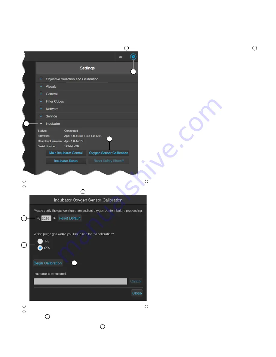
Calibrate the O
2
sensor (EVOS
™
M5000 Imaging System)
1.
Plug the power cord into the power input jack on the control unit and the wall outlet.
2.
Connect the control unit and the computer with the USB cable, then plug the 6-pin sensor data cable from the environmental chamber into
the appropriate input jack on the control unit.
3.
Re-attach the gas lines (Air and Nitrogen or CO
2
) via the PTC (push-to-click) connectors to the control unit, then turn on the valves on the gas
tanks and regulators.
4.
First turn on the EVOS
™
Onstage Incubator, then power on the EVOS
™
M5000 Imaging System.
5.
Start the EVOS
™
M5000 Software, click the
Settings
button
1
in the upper right of the screen, then click to open the
Incubator
menu
2
.
Common Callouts and Arrows
1. Copy-paste a callout or arrow to use in this SVG.
Note: If you need more advanced callouts or arrows
use the TechComm_Inkscape_Callout&Arrow_Libary.
3. Delete this text, this rectangle, and unused
callouts, arrows, or other SVG elements
before adding this SVG to the repository.
2. Edit number and/or line-length, as needed.
1
1
1
1
1
2
3
1
Settings button
2
Incubator menu
3
Oxygen Sensor Calibration button
6.
Click
Oxygen Sensor Calibration
3
in the
Incubator
menu to open the
Incubator Oxygen Sensor Calibration
window.
Common Callouts and Arrows
1. Copy-paste a callout or arrow to use in this SVG.
Note: If you need more advanced callouts or arrows
use the TechComm_Inkscape_Callout&Arrow_Libary.
3. Delete this text, this rectangle, and unused
callouts, arrows, or other SVG elements
before adding this SVG to the repository.
2. Edit number and/or line-length, as needed.
1
1
1
1
1
2
3
1
Oxygen %
2
Purge gas selection
3
Begin Calibration button
7.
Set the
O
2
%
1
to the oxygen content of the air used by the system.
Note:
The default value for
O
2
%
is 20.95% for normal compressed air.
8.
Select the purge gas to use:
Nitrogen
or
CO
2
2
.
EVOS
™
Onstage Incubator O
2
Sensor Replacement Kit
5


