background image

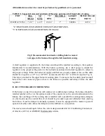
All installations and services must be performed by qualified service personnel. 


11 


3. 


The sequence of operation of the furnace. 


4. 


The  correct  operation  and  maintenance  of  the  appliance  as  outlined  in  the users information 
manual. 


5. 


That  failure  to maintain and operate this furnace in accordance with these instructions could 
result  in  hazardous  conditions,  bodily  injury,  property  damage  and  may  void  the  limited 
warranty on the furnace. 


6.  

Review  with  and  encourage  the  user  to  read  the  label  reproductions  and  all  warnings  and 
instructions outlined in this Manual.


Recommend that the user have a qualified heating contractor inspect the furnace at the start of 
each heating season. Inform the user of the frequency of inspection required for each item in 
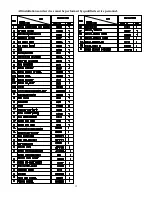
Section III of the User’s Manual


III. USERS INFORMATION SECTION 
A. COMBUSTION AIR SUPPLY:

 The burner requires a generous amount of clean combustion 

air to operate safely. Lack of adequate combustion air can result in erratic operation of the burner, 
noisy combustion, or fuel odors in the air. Never block the furnace from the supply of combustion 
air.  If  there  is  an  exhaust  fan,  dryer  or  return  air  grill  in  the  furnace  room,  there  should  be 
increased  concern  and  additional  efforts  may  be  required  to provide adequate combustion oil to 
the furnace at all times.  

 
B. OIL SUPPLY: 

Do not allow the fuel tank to run completely empty. During the summer, keep 

the tank full to prevent condensation of moisture on the inside surface of the tank. If the fuel tank 
runs  completely  dry,  it  may  be  necessary  to  purge  the  lines  of  trapped  air.  Contact  a  qualified 
technician  to  bleed  the lines and restart the burner. Turn the oil supply valve off if the burner is 
shut down for an extended period of time. 
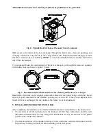
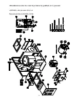
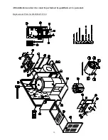
 

C. INSPECTION AREAS 
VESTIBULE:   

The  furnace  vestibule  area  or  burner  compartment  should  be  inspected  by 

removing  the  front  door  of  the  furnace  and  looking  for  signs  of  excessive  heat  such  as 
discoloration of components materials damage, from rust or corrosion, soot or carbon build-up. 
 

EXTERIOR  OF  FURNACE:   

The  furnace  exterior  should  be  inspected for signs of excessive 

heat such as discoloration of materials and damage from rust or corrosion. 
 

FLUE PIPE, VENT PIPE OR CONNECTOR:  

The furnace vent pipe should be inspected for 

signs  of  rust,  corrosion  pitting  or  holes  in  pipe,  and  leakage  around  seams  in  pipe,  indicated by 
soot or condensate streaks. 

 
CHIMNEY  OR  VENTING  SYSTEM:   

The  furnace  venting  system  should  be  inspected  for 

signs of rust, corrosion pitting or holes, and signs of condensation or moisture leakage from the 
venting system. 
 
If any of the above symptoms are evident, call a qualified heating contractor for assistance. 

Summary of Contents for OL20FA151T60 Series

Page 1: ...THE VICINITY OF THIS OR ANY OTHER APPLIANCE c WARNING IMPROPER INSTALLATION ADJUSTMENT ALTERATION SERVICE OR MAINTENANCE CAN CAUSE INJURY OR PROPERTY DAMAGE REFER TO THIS MANUAL FOR ASSISTANCE OR ADDI...

Page 2: ......

Page 3: ...y result in personal injury substantial property damage or death See Page 9 cWARNING The heat exchanger must be cleaned by a qualified service person See Page 9 cCAUTION DO NOT ATTEMPT TO MAKE REPAIRS...

Page 4: ...s must be performed by qualified service personnel ii This page contains reproductions of the various instruction and warning labels placed on the Thermo Pride Oil Furnaces Please read and comply with...

Page 5: ...All installations and services must be performed by qualified service personnel iii...

Page 6: ...UNIT 7 A INITIAL STARTUP 7 B BURNER ADJUSTMENT 7 C AIRFLOW AND TEMPERATURE RISE 8 VI TROUBLESHOOTING AND SERVICE 9 A FAN CONTROL 9 B LIMIT POSITION AND LOCATION 9 C BURNER TROUBLSHOOTING 9 D HEAT EXC...

Page 7: ...furnace installed in a residential garage must be installed so the burner and ignition source are located higher than 18 inches above the floor unless the required combustion air is taken from the ex...

Page 8: ...ccordance with local codes and the Standard for the Installation of Oil Burning Equipment NFPA 31 2001 or the latest editions thereof ROTATION OF FRONT FLUE ELBOW On the front flue lowboy it is possib...

Page 9: ...the overfire draft should be a negative 01 to 02 WC as measured at the 5 16 overfire air tap See Fig 3 This tap is provided in the upper burner mounting plate To measure the flue draft punch a small...

Page 10: ...OTICE Remove all cardboard packing from around chamber before installing burner The oil burner will mount on three stud mounting bolts on the lower mounting plate covering the opening in the front of...

Page 11: ...ULATION DOWN The loose fill insulation should be placed in such a fashion that the surface of the insulation is sloped from the top of the combustion chamber to the top of the lower mounting plate The...

Page 12: ...rd for the Installation of Oil Burning Equipment NFPA 31 2001 and the oil burner operating instructions for detailed information on oil storage tank oil supply return line installation NOTICE We recom...

Page 13: ...mporary air adjustment for a clean smoke free flame At this point the final burner adjustment should be made using test instruments to measure oil pump pressure smoke number carbon dioxide CO2 carbon...

Page 14: ...input rate or reducing the amount of supply return airflow 1Cycle the furnace several times to verify the burner lights off and shutdown smoothly without excessive noise or smoke production Table 2 O...

Page 15: ...ON cWARNING The predetermined fan and limit locations on all of the Thermo Pride oil fired furnaces have been tested and approved by Thermo Products LLC Any attempt to relocate these safety controls o...

Page 16: ...r cleaning inside of heat exchanger Reassemble the furnace to its original construction Remount the burner being certain that the air tube is properly inserted into the chamber opening see section D I...

Page 17: ...s may be required to provide adequate combustion oil to the furnace at all times B OIL SUPPLY Do not allow the fuel tank to run completely empty During the summer keep the tank full to prevent condens...

Page 18: ...mperature 3 Open shut off valves in oil supply line to burner 4 Turn service switch to furnace ON If burner starts and runs but stops again on lockout it may be necessary to bleed the lines or make bu...

Page 19: ...All installations and services must be performed by qualified service personnel 13...

Page 20: ...All installations and services must be performed by qualified service personnel 14 APPENDIX A Replacement Parts List Replacement Parts for OL20FA151T60...

Page 21: ...All installations and services must be performed by qualified service personnel 15...

Page 22: ...All installations and services must be performed by qualified service personnel 16 Replacement Parts for OL20RA151T60...

Page 23: ...All installations and services must be performed by qualified service personnel 17...

Page 24: ...All installations and services must be performed by qualified service personnel 18 Replacement Parts for Beckett Burner...

Page 25: ...All installations and services must be performed by qualified service personnel 19 Replacement Parts for Riello F5 Burner...

Page 26: ...All installations and services must be performed by qualified service personnel 20 APPENDIX B Wiring Diagrams...

Reviews: