58
Beckett
Burner
Riello Burner
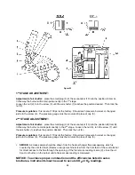
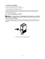
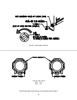
Figure 28: Location of oil primary control reset button
If this action does not reactivate the unit, contact a qualified service agency for assistance.
In general, if the thermostat is set in the heating mode, the heating system functions entirely
automatically. However, under certain circumstances, the appliance may not be able to fire the burner.
For instance, if the manual oil shutoff valve has been closed or the oil tank is out of fuel, the oil line may
have air trapped in it. It will be necessary to purge the air by bleeding the supply line from the tank to the
burner again for the heating system to operate. Refer to the instructions under the
Extended Appliance
Shutdown
section of this manual.
NOTICE: Thermo Products recommends that the user/homeowner, contact a qualified service
agency for assistance in bleeding the fuel line(s) and lighting off the heating section.
The following maintenance points should be reviewed periodically to assure the heating and cooling
systems continue to function properly.
:
Shut off unit and disconnect the power source before disassembling the unit.
:
Never operate the appliance without clean air filters in place.
: This appliance requires air for combustion, ventilation, and cooling. Do not block or
obstruct air openings in the unit and the air space around the perimeter of the unit.
1. At least every three months, under normal usage conditions, check and clean all air filters in the
appliance and, if present, in the duct system. If excessively dirty air filters are not cleaned, or
changed, poor system performance will result due to reduced airflow. Low airflow places
unnecessary strain on the compressor, possibly causing the system to shutdown on the
refrigerant high-pressure switch. Refer to Figure 23 for a sketch of the filter location.
2. Do not allow the fuel oil tank to run completely empty. During the summer, keep the tank full to
reduce condensation of moisture on the inside surface of the tank. If the fuel tank runs
completely dry, it may be necessary to bleed air from the fuel lines.
Contact a qualified heating
contractor to bleed the lines and restart the burner.
3. Check the supply and return air connections to the appliance to insure the seals between the
duct and appliance and the appliance and home are intact. Check the ducts for any signs of
collapse, holes, or excessive corrosion. Repair or replace components as required.
VII. TROUBLESHOOTING:
THIS SECTION IS ONLY TO BE PERFORMED BY TRAINED, QUALIFIED SERVICE
PERSONNEL, AND NOT BY THE FURNACE OWNER.
NOTICE: Before troubleshooting, familiarize yourself with the Initial Startup,
Checkout Procedure, and Troubleshooting Flowchart.
Refer to the appendices of this manual for an electrical schematic, a connection diagram, flowcharts to
assist in troubleshooting, product specifications, and a replacement parts list follow for this appliance.
Summary of Contents for OH6FA072D48N
Page 5: ...2...
Page 33: ...30 Heating Speed Set ups 2 Stage OH6FX072DV4 Figure 18 2 ECM 2 stage blower motor speed chart...
Page 64: ...61 VIII Sequence of Operations Flow Chart...
Page 65: ...62...
Page 66: ...63 IX Trouble Shooting Flow Chart...
Page 67: ...64...
Page 68: ...65...
Page 69: ...66...
Page 70: ...67...
Page 72: ...69 Appendix A Replacement Parts Replacement Parts for OH6FA072D...
Page 73: ...70 Replacement Parts for OH8FA119D...
Page 74: ...71 Appendix B Wiring Diagrams OH6FA072D48 PSC Wiring Diagram...
Page 75: ...72 OH6FA072DV4 ECM Wiring Diagram...
Page 76: ...73 OH6FX072DV4 ECM 2 Stage Wiring Diagram...
Page 77: ...74 OH8FA1119D60 PSC Wiring Diagram...
Page 78: ...75 OH8FA1119DV5 ECM Wiring Diagram...
Page 79: ...76...

