56
ON STARTUP:
1. Have system inspected and started by a qualified heating contractor.
2. Check oil level in tank. If the tank has not been filled with fresh oil, inspect the remaining oil for
signs of contamination with water, algae, dirt or other impurities. If excessive, consult your oil
supplier for recommendations.
3. Change the oil filter cartridge and clean the canister.
4. Set the room thermostat above room temperature.
5. Open all valves in the oil supply
line.
6. Open the inspection cover on the upper mounting plate.
7. Turn on the electrical power to start the burner. If the burner does not start, immediately reset the
manual overload switch on the motor (if so equipped) and the safety switch of the burner
primary control. Bleed air from the fuel oil line as soon as the burner motor starts rotating. To
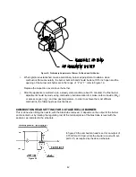
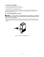
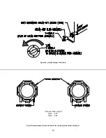
bleed the fuel pump, attach a clear plastic hose over the vent plug, refer to Figure 27. Loosen
the plug and catch the expelled oil in an empty container. Tighten the plug when all the trapped
air appears to be purged. If the burner stops during bleeding, wait three to five minutes for the
control safety switch to cool. Then manually reset the switch. Continue bleeding the line until the
air is completely removed.
Figure 27: Location of Oil Pump Vent Plug
8. Follow the previous
Initial Burner Operation
procedures.
VI. HOMEOWNER/USER INFORMATION AND ROUTINE MAINTENANCE:
c
WARNING: Never burn garbage or refuse in this appliance. Never try to ignite
oil by tossing burning papers or other material into the combustion chamber.
c
WARNING: Oil-fired appliances produced by Thermo Products are designed for
burning No. 2 distillate (domestic heating) fuel oil. Never use gasoline or a
mixture of oil and gasoline.
Summary of Contents for OH6FA072D48N
Page 5: ...2...
Page 33: ...30 Heating Speed Set ups 2 Stage OH6FX072DV4 Figure 18 2 ECM 2 stage blower motor speed chart...
Page 64: ...61 VIII Sequence of Operations Flow Chart...
Page 65: ...62...
Page 66: ...63 IX Trouble Shooting Flow Chart...
Page 67: ...64...
Page 68: ...65...
Page 69: ...66...
Page 70: ...67...
Page 72: ...69 Appendix A Replacement Parts Replacement Parts for OH6FA072D...
Page 73: ...70 Replacement Parts for OH8FA119D...
Page 74: ...71 Appendix B Wiring Diagrams OH6FA072D48 PSC Wiring Diagram...
Page 75: ...72 OH6FA072DV4 ECM Wiring Diagram...
Page 76: ...73 OH6FX072DV4 ECM 2 Stage Wiring Diagram...
Page 77: ...74 OH8FA1119D60 PSC Wiring Diagram...
Page 78: ...75 OH8FA1119DV5 ECM Wiring Diagram...
Page 79: ...76...

