


44
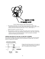
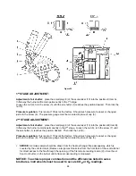
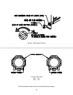
Figure 22
1
st
STAGE ADJUSTMENT:
Adjustment of air shutter:
place the small plug (9) of the economizer (10) into the position
I
(Item A).
In this way the burner will remain permanently in the 1
st
stage.
Loosen the nut (2), turn the screw (3) until the air shutter (1) reaches the position desired. Then lock the
nut (2).
Pressure regulation:
this is set at 130 psi at the factory. Should such pressure be reset or changed,
just turn the screw (4). The pressure gauge must be mounted in place of cap (5).
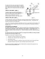
2
nd
STAGE ADJUSTMENT:
Adjustment of air shutter:
place the small plug (9) of the economizer (10) into the position
II
(Item B).
In this way the burner remains permanently in the 2
nd
stage. Loosen the nut (6), turn the screw (7) until
the air shutter (1) reaches the position desired. Then lock the nut (6).
Pressure regulation:
this is set at 170 psi at the factory. Should such pressure be reset or changed,
just turn the screw (8). The pressure gauge must be mounted in place of cap (5).
i.
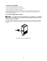
SMOKE:
A smoke sample should be drawn from the heat exchanger flue passageway, which is
covered by the vent terminal. (Remove a large machine screw from the front face of the vent terminal
for direct access to the flue through the opening.) If the first smoke reading is zero (0), close the air
band, or shutter, on the burner until a trace smoke reading is measured.
NOTICE: To achieve proper combustion and the efficiencies listed in sales
brochures, instruments must be used to secure CO2
or O2
readings.
Summary of Contents for OH6FA072D48N
Page 5: ...2...
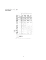
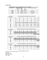
Page 33: ...30 Heating Speed Set ups 2 Stage OH6FX072DV4 Figure 18 2 ECM 2 stage blower motor speed chart...
Page 64: ...61 VIII Sequence of Operations Flow Chart...
Page 65: ...62...
Page 66: ...63 IX Trouble Shooting Flow Chart...
Page 67: ...64...
Page 68: ...65...
Page 69: ...66...
Page 70: ...67...
Page 72: ...69 Appendix A Replacement Parts Replacement Parts for OH6FA072D...
Page 73: ...70 Replacement Parts for OH8FA119D...
Page 74: ...71 Appendix B Wiring Diagrams OH6FA072D48 PSC Wiring Diagram...
Page 75: ...72 OH6FA072DV4 ECM Wiring Diagram...
Page 76: ...73 OH6FX072DV4 ECM 2 Stage Wiring Diagram...
Page 77: ...74 OH8FA1119D60 PSC Wiring Diagram...
Page 78: ...75 OH8FA1119DV5 ECM Wiring Diagram...
Page 79: ...76...


