Environmental Chamber ________________________________________________________________Installation and Set-Up
2 - 3
If the battery is weak or not connected, the green LED will
flash. If power is lost to the cabinet, the LED will also flash.
When replacing the 9-volt battery, use only an alkaline style
battery. Dispose of the old battery following established envi-
ronmental practices.
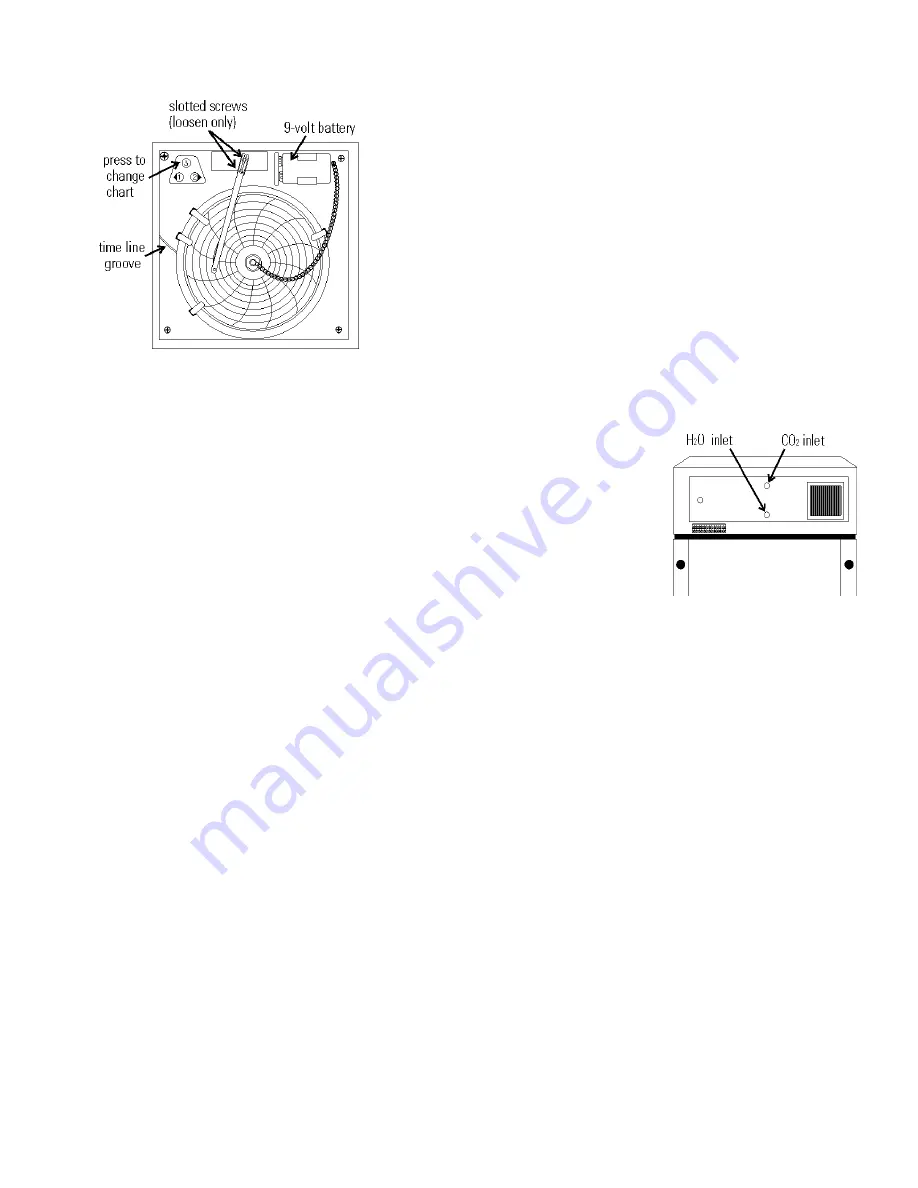
b. Changing the Chart Paper
1. Press the Change Chart button (#3) and hold it for 1 sec-
ond until the pen begins to move to the left of the chart.
See Figure 2-4.
2. Remove the existing chart by unscrewing the center
knob securing it.
3. Install the new chart, positioning it so that the correct
time line coincides with the time line groove on the
chart plate.
4. Replace the center knob and screw it tightly against the
chart.
c. Changing the Pen
1. Using a small flat blade screwdriver, loosen the 2 screws
holding the pen arm and remove the pen and arm as an
assembly.
2. Unsnap the plastic hinge securing the pen. Remove and
discard the old pen.
3. Install the new pen by snapping the hinge securely
around the pen arm.
4. Re-install the pen assembly by sliding the pen arm under
the screws, positioning the pen tip in the time line
groove. Tighten the screws.
5. Push the Chart Change button and hold it for 1 second
until the pen begins to move back onto the chart.
Note
: Make sure that the pen is marking on the chart. It may
be necessary to gently lift the pen onto the chart paper.
2.9 Honeywell Recorder (optional)
The Honeywell, DR 4500 Recorder is a one to four-chan-
nel microprocessor-based, circular chart recorder.
The recorder is capable of recording both temperature and
humidity and printing alphanumeric chart data on blank heat-
sensitive chart. Refer to the Honeywell Configuration Record at
the end of Section 5 and the supplemental Honeywell Recorder
manual.
2.10 IR CO
2
Option
This section applies to units with the IR CO
2
option only.
a. Connecting the CO
2
Source (Figure 2-5)
For the most economical
use, the liquid CO
2
supply
tanks should be without
siphon tubes, so that only CO
2
gas enters the incubator injec-
tion system. Two tanks may
be joined together with a man-
ifold to ensure a continuous
CO
2
supply.
Install a two-stage pres-
sure regulator, with indicating gauges, at the supply cylinder
outlet. The high-pressure gauge should have an indicating range
of 0 to 2000 psig to monitor tank pressure. The low-pressure
gauge should have an indicating range of 0 to 30 psig to moni-
tor input pressure to the incubator injection system. A suitable
two-stage pressure regulator is available.
The CO
2
source must be regulated at a pressure level
between 5 and 10 psig. Higher pressure levels may damage the
CO
2
control system. The user should determine the most eco-
nomical pressure level, between 5 and 10 psig appropriate for
the desired CO
2
percentage in the chamber. Use only sufficient
pressure to maintain recovery time after door openings.
To connect the CO
2
supply:
1. Insert the copper tubing provided with the unit as far as
it will go into the nut of the CO
2
connection.
2. Turn the nut until it is finger tight.
3. For reference, scribe the nut at the 6:00 position.
4. While holding the fitting body steady with a wrench,
tighten the nut 1-1/4 turns until the mark is at the 9:00
position.
5. Securely attach the CO
2
line to the open end of the cop-
per tubing.
6. Check the tubing connection for leaks.
Figure 2-5
Figure 2-4


