background image


Safety measures


3/48


Safety measures


a. General instructions 


The system operator should:


- Keep this manual carefully.


- Make sure that the collectors cannot be accessed by unauthorized 
or unaccompanied persons (minors, non-maintenance personnel 
etc.).


b. Installation instructions 


Installation, charging, maintenance and repairs must only be carried out by a qualified 
installer, in compliance with the following safety instructions:


-  Comply with current legislation of each country regarding accident prevention and 

environmental safety.


-  Install the entire solar system according to the current regulations and recognized 

technical practices for the installation of such equipment.


-  Follow  the  accident  prevention  regulations  established  by  professional  trade 

associations, in particular the wearing gloves and protective goggles to avoid injury 
and a safety harness, which should be anchored to the lifeline, when working roofs.


-  Do not carry out repairs on components that have safety functions. These must be 

periodically checked and, if necessary, replaced.


-  Components must only be replaced using Thermics Energie original spare parts. 

Failure to do so will void the warranty.


-  Avoid contact with high temperature components or with escaping steam as they 

can cause scalds or burns.


-  Only remove the protective film from the collector after the solar system has been 

charged and put into operation. Give the film to the user so that it can be reused.


Summary of Contents for 10 DTH V2

Page 1: ...Code 8TAV00005 INSTALLATION MANUAL 10 DTH V2 Forced circulation systems ...

Page 2: ...sport and handling j Choice of hydraulic connection and examples k Installation methods l Standard support composition m Flat roof installation with trestle n Installation with brackets o Hydraulic system assembly p Charging the solar circuit and putting it into operation page 12 page 13 page 14 page 19 page 19 page 25 page 29 page 31 page 36 Panel maintenance and repair page 39 q Annual inspectio...

Page 3: ...nical practices for the installation of such equipment Follow the accident prevention regulations established by professional trade associations in particular the wearing gloves and protective goggles to avoid injury and a safety harness which should be anchored to the lifeline when working roofs Do not carry out repairs on components that have safety functions These must be periodically checked a...

Page 4: ...these instructions carefully Use the fixing systems provided by the manufacturer and use suitable tools for installing them Installation must only be carried out by qualified personnel according to the national and regional regulations in force Only use the fixing systems provided for the Thermics Energie collectors and read the current regulations provided in these instructions in order to instal...

Page 5: ... also its ability to optimize the efficiency of the entire solar field are a fundamental aspect for the economics of the investment The specific design objectives of the Thermics Energie solar collector allows the carrier fluid distribution lines to be simplified and significantly reduced and the available spaces to be optimized The Thermics Energie solar collector is a robust high quality product...

Page 6: ...iption of label The following label on the panel located at the top right of the frame is as follows 1 Manufacturer details 2 Product details 3 Solar Keymark certification label 4 Panel name 5 Technical information e Panel overview ...

Page 7: ...ium panel frame 4 Evacuated tube seal 5 Blank end cap 6 End cap with holes 7 Water connections f Panel technical specifications Model 10 DTH V2 N Tubes 10 L1 net 1150mm L2 net 1166mm Net area 2 09 sq m Gross area 2 38 sq m Fluid volume 2 23 l Dry weight 52 Kg Connections Copper Dn22 ...

Page 8: ...Panel description 8 48 Pressure drop ...

Page 9: ... it is 90 Maximum recommended orientation 30 south east 30 south west If the orientation of the roof pitch is greater than 30 with respect to the south you can also consider installing it on a double EAST WEST pitch It is very important to make sure that there are no obstructions on the horizon line that could affect the irradiation of the collector during the transit of the sun Any obstructions s...

Page 10: ...system Fluid volume of the panel installed Capacity of the solar circuit expansion vessel The amount of antifreeze contained in each metre of tubing copper The amount of antifreeze contained in each metre of tubing stainless steel The amount of antifreeze for each boiler installed 10 DTH V2 2 23 l 1 3 DN 18 0 20 litres DN 16 0 29 litres 6 litres from 200 to 300 L Solar circuit expansion vessel To ...

Page 11: ...ing 200L 2 38 sq m 170 l h 1 Copper 18 mm 300L 4 76 sq m 228 l h 2 Copper 18 mm 500L 7 14 sq m 340 l h 3 Copper 18 mm 800L 11 90 sq m 569 l h 5 Copper 22 mm 1000L 14 28 sq m 681 l h 6 Copper 22 mm 1500L 21 42 sq m 1022 l h 9 Copper 22 mm 2000L 28 56 sq m 1363 l h 12 Copper 28 mm Note For complex systems with particular dimensions and characteristics specific calculations have to be made in order t...

Page 12: ...collector should be taken into account in the calculations for evaluating the load stress from single and combined loads due to wind and snow The solar collector has been designed to withstand the most severe combined wind and snow conditions that are characteristic of Italy as required by the reference standard However if load situations that exceed the maximum load of the panel are expected it i...

Page 13: ...re manual bleed valves at the highest points of the solar circuit to be able to bleed the entire circuit After installing the products make sure that the pre charge pressure of the vessel complies with that of the project Make sure that the probes are correctly connected to the control unit Make sure that the control unit is correctly connected to the power circuit and that the parameter settings ...

Page 14: ... Energie panels can be connected in series in a battery having a total surface area up to 35 sq m The hydraulic inlet and outlet connections to the panel can be installed one on one side and one on the other either on the right or left or both on the same side either right or left ...

Page 15: ...Panel installation 15 48 The following connection possibilities are available for 10 DTH V2 panels Conditions of use and period of use ...

Page 16: ...al that sufficient space is provided to allow operator access the space between one battery and another Key to details and connection examples Detail Description A Curved or straight compression fitting for copper pipe Dn22 Compression T fitting with thermowell for copper pipe Dn22 B Straight compression fitting for copper pipe Dn22 C Caps for copper pipe Dn22 D Curved or straight compression fitt...

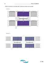
Page 17: ...Panel installation 17 48 Series of collectors connected with Tichelman reverse return system ...

Page 18: ... pipe Dn22 Cap for copper pipe Dn22 D Curved or straight compression fitting for copper pipe Dn22 Cap for copper pipe Dn22 Detail Description A Quick coupling 4 way fitting with stainless steel copper probe thermowell Dn 16 x 22 B Straight copper copper pipe fitting Dn 22 x 22 C Quick coupling for copper stainless steel pipe Dn 22 x 22 D Quick coupling for copper stainless steel pipe Dn 22 x 22 th...

Page 19: ...ng to the anchoring surface available pitched roof and long screws or brackets pitched roof and trestle flat roof and trestle façade l Standard support composition In order for the Thermics Energie panels to be installed correctly please follow the instructions below for positioning the brackets on a sloping roof ...

Page 20: ...Panel installation 20 48 ...

Page 21: ...Panel installation 21 48 ...

Page 22: ...n pitched roof brackets Installation of one 10 DTH V2 collector Panel A max mm C max mm 10 DTH V2 640 1600 Note The slot at the bottom of the Double T bracket allows the value of C to be varied according to the anchoring requirements of the substrate The installation of a single collector requires 2 kits per collector installed ...

Page 23: ...el A max mm C max mm 10 DTH V2 820 1600 Note The slot at the bottom of the Double T bracket allows the value of C to be varied according to the anchoring requirements of the substrate The installation of two collectors in series requires 1 bracket kit per n collectors in series 1 ...

Page 24: ... mm A1 max mm C max mm 10 DTH V2 820 1024 1600 Note The slot at the bottom of the Double T bracket allows the value of C to be varied according to the anchoring requirements of the substrate The installation of three or more collectors in series requires 2 bracket kits per n collectors in series 1 ...

Page 25: ...Panel installation 25 48 m Flat roof installation with trestle ...

Page 26: ...l on flat roof brackets are shown below Installation of one 10 DTH V2 collector Panel A max mm C max mm 10 DTH V2 640 2020 Note As explained above you should select the angle required before installing the kits The installation of a single collector requires 2 kits per collector installed ...

Page 27: ... V2 collectors in series Panel A max mm C max mm 10 DTH V2 820 2020 Note As explained above you should select the angle required before installing the kits The installation of two collectors in series requires 1 bracket kit per n collectors in series 1 ...

Page 28: ...lectors in series Panel A max mm A1 max mm C max mm 10 DTH V2 820 1024 2020 Note As explained above you should select the angle required before installing the kits The installation of three or more collectors in series requires 1 bracket kit per n collectors in series 1 ...

Page 29: ...Panel installation 29 48 n Installation with brackets ...

Page 30: ...Panel installation 30 48 ...

Page 31: ...Panel installation 31 48 o Hydraulic system assembly Both sides of the Thermics Energie panel have a delivery and a return connection DN22 ...

Page 32: ...a delivery and as a return the corresponding connection on the other side will be closed with the cap Detail of the curved or straight compression fitting connection at the input to the panel Detail of the connection of the compression T fitting with thermowell at the outlet from the panel Note If the inlet or outlet pipe is Dn 18 the reduction bush that is included in the Thermics Energie systems...

Page 33: ...tainless steel hose Depending on the type of connection the panel can be connected on the right or left with delivery and return on different sides or with the delivery and return on the same side Each connection can also be used both as a delivery and as a return the corresponding connection on the other side will be closed with the cap ...

Page 34: ...ich the hot delivery line to the heating system starts The probe itself must be inserted so that it touches the bottom of the well taking care to secure it in place using the tightening nut included in the fitting If the probe is installed Incorrectly the temperature readings may be incorrect making the system inefficient Detail of connecting panels with straight compression fitting Important The ...

Page 35: ...1 Note When installing the solar station using copper pipe we recommend using the fitting shown in the first and second photos including the HT seal available as an accessory Also in this case if the inlet or outlet pipe is Dn 18 a reduction bush can be used which can be purchased as a separate accessory For coil lengths of greater than 6 metres expansion joints e g stainless steel bellows should ...

Page 36: ... corrosion inhibitor additives can be used If treated water desalinated etc is used this must meet the following chemical characteristics Please follow the instructions below in order to charge and operate the Thermics Energie panels correctly Treated water characteristics CI 50 ppm SO4 100 ppm Absence of NH4 PH 7 Hardness 12 f Detail Description 1 Safety valve 2 Pressure gauge 3 Vessel hose conne...

Page 37: ... clockwise by 45 C to stop adding the washing fluid and the empty the system Close the filling and drain valves 5 9 Turn the thermometer 13 anticlockwise by 45 C Open the ball valve 10 by turning it anticlockwise and screw the caps 6 8 back on the two valves 5 9 Empty the fluid from the entire circuit by turning the thermometer 13 clockwise by 45 C open the valves 5 9 and remove the two caps 6 8 W...

Page 38: ...r fields If the solar line contains a diverter valve make sure it is open in manual mode to allow the antifreeze to circulate in both circuits After having done this put the valve back to automatic mode Quickly open and close the thermometer 13 for a few seconds remembering to leave it in the open position after having done so Close the drain valve 9 and open the ball valve 10 Bring the system up ...

Page 39: ...ports that could cause abnormal movements Check the insulation of the tubes and replace any defective ones if necessary Use a special tester to check the effectiveness of the antifreeze before the onset of winter Check the system pressure paying attention to anything that may cause a pressure drop system leaks vessel pre charge too low discharge from the safety valve Check the anti corrosive prope...

Page 40: ...ion without causing the safety valves to open and vent Safety valve Each solar station that has a circulation pump is fitted with a safety valve with a threshold pressure of 6 bar The theoretical maximum pressure that can be reached within the solar circuit is set using this device ...

Page 41: ...ction system connect the frame to the existing equipotential conduit The connection must also intercept the delivery and return pipes in addition to the frame For very large solar systems consider a connection to the equipotential conduit for every 200 sq m s Faulty or damaged evacuated tube replacement Warning For systems with solar fields of 15m2 or for large solar fields it is necessary to prov...

Page 42: ...Panel maintenance and repair 42 48 Remove the lid of the frame Lift the tube to be replaced just enough to remove it Lift and remove the tube to be replaced from the head with the hydraulic connections ...

Page 43: ... regulations in force The packaging and accessories can be disposed of by the installer who assembles the system while the disposal of the collector at the end of its service life is the responsibility of the owner Alternatively it can be done by Thermics Energie who will collect and dispose of it at a recycling centre any removal shipping or other costs associated with collection will be charged ...

Page 44: ...44 48 ...

Page 45: ...45 48 ...

Page 46: ...46 48 ...

Page 47: ...47 48 ...

Page 48: ...quarters Via C Pascoletti 2 33040 Povoletto UD Italy Tel 39 0432 823600 Fax 39 0432 825847 www thermics energie it info thermics energie it All rights reserved Thermics Energie reserves the right to modify and update this document 29 04 2021 Rev 00 Cod 8TAV00005 ...

Reviews: