

23
22
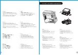
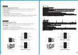
Guide d'installation des fils
Connexion des voyants du boîtier
/ Sur la face avant du boîtier, vous trouverez plusieurs voyants et les fils des
boutons. S'il vous plaît consultez le guide d'utilisateur du fabricant de votre carte mère, puis connectez ces fils aux
onnecteurs sur la carte mère.
Connexion USB 2.0
/ S'il vous plaît consultez le manuel de votre carte mère à la section "Connexion USB"
Connexion USB 3.0
/
1. Vérifiez que votre carte mère prend en charge la connexion USB 3.0.
2. Connectez le câble USB 3.0 au port USB 3.0 disponible sur votre ordinateur.
Connexion Audio
/ S'il vous plaît référez vous à l'illustration suivante du connecteur audio et au guide de l'utilisateur de
votre carte mère. S'il vous plaît sélectionnez une carte mère supportant AC'97 ou HD Audi (Azalia), (faites attention que
votre audio supporte l'AC'97 ou HD Audio (Azalia)) sinon cela pourrait endommager votre matériel.
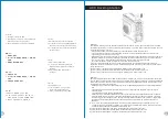
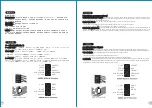
Guía de Instalación de Cables
Conexión del LED de la caja
/
En la parte frontal de la caja, encontrará algunos LED y cables de interruptores. Consulte
el manual del usuario del fabricante de la placa madre, a continuación conecte estos cables al conector de la placa madre.
Conexión USB 2.0
/
Consulte el manual de la placa madre para obtener más información sobre el apartado “Conexión USB"
Conexión USB 3.0
/
1. Asegúrese de que la placa base admite conexión USB 3.0.
2. Conecte el cable USB 3.0 al puerto USB 3.0 disponible en el equipo.
Conexión de Audio
/
Consulte la siguiente ilustración del conector de Audio y el manual del usuario de la placa madre.
Seleccione la placa madre que utiliza AC’97 o HD Audio (Azalia), (asegúrese de que su audio admite AC’97 o HD Audio
(Azalia)) si no, sus dispositivos resultarán dañados
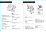
USB 3.0 Connection
L-OUT
SENSE
R-OUT
MIC-POWER
MIC-IN
SENSE2
KEY
SENSE1
PRESENSE
GND
L-OUT
R-OUT
MIC-POWER
MIC-IN
L-RET
KEY
R-RET
GND
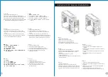
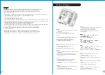
Leads Installation
Leads Installation Guide
Case LED Connection
/ On the front of the case, you can find some LEDs and switch leads. Please consult your user
manual of your motherboard manufacturer, then connect these leads to the panel header on the motherboard.
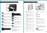
USB 2.0 Connection
/ Please consult your motherboard manual to find out the section of “USB connection”.
USB 3.0 connection
/
1. Make sure your motherboard supports USB 3.0 connection.
2. Connect the USB 3.0 cable to the available USB 3.0 port on your computer.
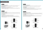
Audio Connection
/ Please refer to the following illustration of Audio connector and your motherboard user manual.
Please select the motherboard which used AC’97 or HD Audio(Azalia),(be aware of that your audio supports AC’97 or HD
Audio (Azalia)) or it will damage your device(s).
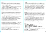
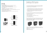
Anschlüsse herstellen
Gehäuse-LED-Verbindungen
/ Auf der Gehäusevorderseite finden Sie einige LEDs und Verbindungen. Bitte nehmen
Sie die Gebrauchsanweisung Ihres Motherboard Herstellers zur Hilfe und schließen Sie diese Verbindungen an die Panel
Header Belegung des Motherboards an.
USB 2.0 Anschluss
/ Bitte nehmen Sie die Gebrauchsanweisung Ihres Motherboards zur Hilfe und lesen Sie unter dem
Kapitel „USB Anschlüsse“ nach.
USB 3.0 Anschluss
/
1. Stellen Sie sicher, dass Ihre Hauptplatine den USB 3.0 Anschluss unterstützt.
2. Verbinden Sie das USB 3.0 Kabel mit dem USB 3.0 Port auf Ihrem Computer.
Audio Anschlüsse
/ Bitte beachten Sie die folgende Abbildung der Audio Anschlüsse und die Anweisung in der
Gebrauchsanweisung Ihres Motherboards. Bitte wählen Sie das Motherboard, das AC’97 oder HD Audio(Azalia)
verwendet, (achten Sie darauf, dass Ihr Audio AC’97 bzw. HD Audio (Azalia unterstützt)). Andernfalls entstehen schwere
Schäden an Ihrem(n) Gerät(en)!!!
USB 3.0 Connection
L-OUT
SENSE
R-OUT
MIC-POWER
MIC-IN
SENSE2
KEY
SENSE1
PRESENSE
GND
L-OUT
R-OUT
MIC-POWER
MIC-IN
L-RET
KEY
R-RET
GND