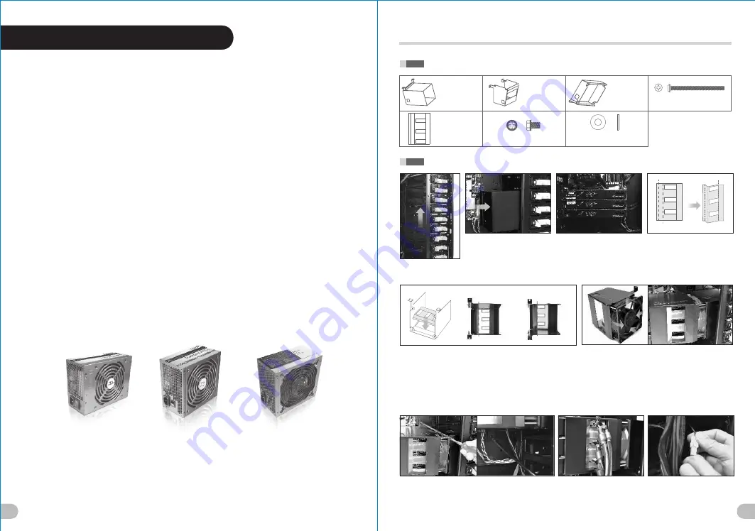
background image

33

Move  the  HDD  iCage 
up  4  bay  drives.

Content on this sheet is additional information for page 21 to page 26 
of Element V NVIDIA Edition's User's Manual

Put  the  Fan  Duct  1  into  the  empty 
5.25”  drive  bays.

(Do  not  secure  the  Fan  Duct  1 
onto  chassis  yet)

Install  the  graphic  cards.

Fold  the  Mylar  along  dotted  line  A
,  dotted  line  B  and  dotted  line  C 
as  shown  above.

A

B

Stick  the  Mylar  inside  of  Fan  Duct  2  as  shown.

-  For  9.6”  graphic  cards: 

Please  align  the  dotted  line  A  along  the  left  edge  of  the  cut-out  hole 
on  Fan  Duct  2.  (Please  note  the  three  cut-out  holes  on  the  Mylar  are 
further  away  from  the  left  edge  of  the  cut-out  on  Fan  Duct  2)

-  For  10.6”  graphic  cards:


Please  align  the  dotted  line  B  along  the  left  edge  of  the  cut-out  hole 
on  Fan  Duct  2.  (Please  note  the  three  cut-out  holes  on  the  Mylar  are 
closer  to  the  left  edge  of  the  cut-out  on  Fan  Duct  2)

Secure  the  120  x  38  mm  fan  on  Fan  Duct  2.
(Please  make  sure  the  airflow  of  the  fan  is  towards  the 
Fan  Duct  2.  The  fan  has  arrow  on  the  side  of  the  casing 
indicating  the  direction  of  airflow).
Place  the  Fan  Duct  2  over  the  graphic  cards  as  shown. 
Make  sure  the  three  cut-out  holes  on  the  Mylar  are  aligned 
with  the  PCI-E  power  connectors  on  the  graphic  cards.
Also  make  sure  the  Fan  Duct  1  covers  the  120  x  38  mm  fan 
firmly.

Secure  Fan  Duct  1  and  Fan  Duct  2  to  the  motherboard  plate 
with  screws.  (Total  of  4  screws)

Connect  the  required  PCI-E 
power  connectors  from  the  power 
supply  to  graphic  cards.

Either  connect  the  3-pin  wire  of 
the  120  x  38


mm  fan  to  the 

motherboard’s  fan  connector  or 
attach  the  3-4


pin  wire  and 

connect  to  PSU  directly.

Part  List

Fan Duct 1

 x 1 pcs

Fan Duct 2

 x 1 pcs

Fan Duct 3

 x 1 pcs

6#32 Screw

 x 4 pcs

(for 120 x 38 mm fan)

Mylar

 x 1 pcs

6#32 Screw

 x 4 pcs

Washer

 x 4 pcs

(for 120 x 38 mm fan, Quad SLI only)

Dotted line A

Dotted line B

3-WAY  SLI  INSTALLATION

(Before)

(After)

Dotted line C

Cut-out  holes  on  Mylar.(Further 
away  from  the  left  edge  of 
cut-out  hole  on  Fan  Duct  2)

Cut-out  holes  on  Mylar.
(Closer  to  the  left  edge  of 
cut-out  hole  on  Fan  Duct  2)

(For 9.6” graphic cards)

(For 10.6” graphic cards)

34

The  Thermaltake  Power  Supply  series  specification  meets  latest  Intel  & 

AMD  dual  &  Quad  core  processors  and  NVIDIA  &  AMD  high  performance 

graphic  cards;  it  offers  plenty  of  functions,  which  mainly  include:

1.  Automatic  Fan  Speed  Control:  All  power  supply  can  detect  the  inside 

     heat  and  automatically  adjust  the  fan  speed  to  provide  adequate  airflow.

2.  Ultra  Silent:  Ball  bearing  fans  with  high  reliability  140mm  or  120mm 

     cooling  fan  and  super  low  acoustic  noise  under  all  load  condition.

3.  Modularized  Cable  Management:  To  eliminate  clutter  and  improve 

     airflow  inside  the  case.

4.  Dedicated  Graphic  Card  Power:  reduce  the  loading  on  current  PSU  and 

     no  need  to  upgrade  current  PSU  while  running  multi  graphic  cards  mode.

The  functions  can  assure  all  Thermaltake  Power  Supply  meets  the  balance 

in  noise  control  and  heat  exhausted.  All  power  supply  provides  complete 

protection  function  as  follow:

1.  Over  power  protection.

2.  Short  circuit  protection  on  all  output.

3.  Over  voltage  protection  /  Under  voltage  protection.

4.  Over  current  protection.

5.  Over  temperature  protection.

Besides,  Thermaltake  enables  the  quality  assurance  of  all  power  supply: 

100%  Hi-POT  and  ATE  Function  Test,  100%  Burn-In  and  AC  Input  cycled 

on/off  under  high  temperature  condition.  Furthermore,  it  has  been  approved 

by 

UL,  CUL,  TUV,  CB,  FCC,  CE,  and  BSMI.

There  are  three  main  products  line  of  Thermaltake  PSU 

which  divided  into  Toughpower,  Purepower  (include 

Purepower  RX)  and  TR2  (include  TR2  RX)  series. 

Please  refer  to 

http://www.thermaltake.com/product/Power/power_index.asp

5.0 Toughpower / Purepower / 
      TR2 power supply series (optional)

Summary of Contents for Element V NVIDIA Edition

Page 1: ...g to their respective companies www thermaltake com Tested To Comply With FCC Standards FOR HOME OR OFFICE USE User s Manual Benutzerhandbuch Mode d emploi Manual del usuario Manuale dell utente 安裝說明書 用戶手冊 ユーザーズマニュアル Руководство пользователя kullanıcı elkitabı EEE Yönetmeliğine Uygundur NVIDIA Edition ...

Page 2: ...erial Color Expansion Slots Motherboards I O Ports LCS Upgradable PSU Adjustable PSU Bridge 12 5 x 5 25 1 x 3 5 with conversion kits 6 x 3 5 1 x 2 5 SECC 7 9 6 x 9 6 Micro ATX 12 x 9 6 ATX 12 x 13 Extend ATX USB 2 0 x 4 eSATA x 1 HD Audio x 1 Support 1 2 3 8 1 4 water tube Standard PS2 PSU Optional v VL200L1W2Z Full Tower 15 kg 33 1 lb 532 x 220 x 537 mm 20 9 x 8 7 x 21 1 inch Open Window Side Pan...

Page 3: ...iente de su clase sin tener que instalar el sistema de conducto de ventilador opcional ni el ventilador de RPM alto Tenga cuidado cuando manipule el ventilador de RPM alto mientras esté encendido ya que puede causar lesiones serias Italiano Thermaltake Element V NVIDIA Edition è progettato per ottimizzare la dissipazione di calore durante la confugurazione delle schede grafiche NVIDIA GeForce GTX ...

Page 4: ...e longueur de la carte complémentaire VGA Vérifiez que la longueur de votre carte complémentaire VGA ne dépasse pas 335 mm Limitación de altura del refrigerador de CPU Asegúrese de que la altura de su refrigerador de CPU no excede los 165 mm 6 5 pulgadas Limitación de longitud de la tarjeta de vídeo adicional Asegúrese de que la longitud de su tarjeta de vídeo adicional no excede los 335 mm 6 2 pu...

Page 5: ...eral izquierdo extraiga los tornillos de la parte trasera de la caja 4 Tire del panel lateral derecho hacia fuera cómo indica la flecha Italiano 1 Per rimuovere il pannello laterale di sinistra rimuovere le viti ad aletta nella parte posteriore del case 2 Premere i pulsanti quindi estrarre il pannello laterale 3 Per rimuovere il pannello laterale di destra rimuovere le viti nella parte posteriore ...

Page 6: ...k the tool free clip on 5 25 HDD cage 4 Insert the 5 25 device into the driver bay and push inward and downward to lock the tool free clip Deutsch 1 Ziehen Sie am unteren Rand der Vorderseitentafel um sie vom Gehäuse zu entfernen 2 Entfernen Sie die Plastikabdeckung des 5 25 Zoll Schachts 3 Drücken Sie einwärts und aufwärts um den Clip ohne Werkzeug auf dem 5 25 Zoll HDD Käfig zu entsperren 4 Führ...

Page 7: ...设备插入驱动器槽中 并向内部 4 5 25 aygıtını sürücü bölmesine 下方压免用工具扣具以将其锁定 yerleştirin ve araçsız kelepçeyi içeri ve aşağı doğru iterek kilitleyin 日本語 1 フロントパネルの下部を引っ張って シャーシから取り外します 2 5 25 ドライブベイのプラスチックカバ ーを取り外します 3 内側および外側に押して5 25 HDDケー ジの工具不要クリップをアンロックしま す 4 5 25 デバイスをドライブベイに差し込 み 上下に押して工具不要クリップをロ ックします 2 3 3 5 HDD Installation English 1 Squeeze and pull out ward the tool free clip 2 Insert HDD by sliding ...

Page 8: ...简体中文 gerektirmeyen klipsi sıkıştırın ve içe 1 按压免工具卡夹并向外拔出 doğru ittirin 2 将硬盘滑入iCage 插入硬盘 3 拧紧螺丝 固定硬盘 4 按压免工具卡夹并向内推 固定iCage 日本語 1 クリップをつまみながら手前に引き上げ ます 2 HDDをスライドさせ iCageに挿入します 3 iCageの両サイドからネジでHDDを固定し ます 4 iCageを元のベイに戻し クリップでベイ に固定します 2 4 2 5 HDD Installation 简体中文 日本語 Русский English 繁體中文 Deutsch 简体中文 将 2 5 硬盘置于正确位置并以螺丝固定 日本語 Français Русский Español Установите 2 5 дюймовый жесткий диск в надлеж...

Page 9: ...n Sie es mit Schrauben Mettez l alimentation dans le bon endroit et sécurisez la avec des vis 2 Fixez le bloc alimentation dans le bon emplacement et securisez le avec des vis 1 Güç kaynağı birimini uygun konuma takı n ve vidalarla sabitleyin Instale la unidad de fuente de 2 PSU yu uygun konuma ayarlayın ve alimentación en el lugar adecuado y vidayla sabitleyin asegúrela con tornillos 2 Ajuste la ...

Page 10: ...tastiera e il blocco di sicurezza del tarafından arka panele yeniden vidalayın mouse quindi fissarli sul pannello posteriore 2 8 Fan Speed Light Control Operation English 1 LED Light Control Press to switch LEDs color Blue Green Red and Single LED Flash 2 Fan Speed Control Turn clockwise for higher fan speed 3 Fan Speed Control Turn counter clockwise for lower fan speed Deutsch 1 LED Helligkeitsst...

Page 11: ...скорости вентилятора 3 Регулятор скорости вентилятора поверните по часовой стрелке для увеличения скорости вентилятора Türkçe 1 Işık Denetimi Işıkların rengini değiştirmek Mavi Yeşil Kırmızı ve Tek Işığı Yanıp Sönen için düğmeye basın 2 Fan Hızı Denetimi Fan hızını artırmak için saat yönünde döndürün 3 Fan Hızı Denetimi Fan hızını düşürmek için saatin ters yönünde döndürün 2 9 Water Bottle Cage In...

Page 12: ...ührung 2 aus Für 9 6 Zoll Grafikkarte Richten Sie die gestrichelte Linie A des Mylar mit der Ventilatordurchführung 2 aus 4 Sichern Sie den 120x38 mm Ventilator auf der Ventilatordurchführung 2 5 Bringen Sie die Ventilatordurchführung 2 auf den 3 Wege Grafikkarten an und sicher Sie sie auf der Hauptplatine mit Schrauben 6 Setzen Sie den Schwamm zwischen den 120x38 mm Ventilator und die Hauptplatin...

Page 13: ...6 显卡 将麦拉的虚线 B 与风扇导风罩2 对齐 对于 9 6 显卡 将麦拉的虚线 A 与风扇导风罩2 对齐 4 将 120x38mm 的风扇固定在风扇导风罩2上 5 将风扇导风罩2 置于 3 Way 显卡上 用螺丝将其固定在主板背板上 6 在 120x38mm 的风扇和主板背板之间置入海绵 以避免漏气 7 将 120x38mm 风扇的 3 PIN 接头源线插入主板的风扇接口 将未使用的电源线接入显卡 日本語 日本語 1 工具不要のクリップを強く握りながら外側に引っ張り iCageを上方に4ベイ分だけ動かします 2 ファンダクト1を空の5 25 ドライブベイのケージに挿入し ねじでマザーボードプレートに固定します 3 グラフィックカードを取り付け 図のようにファンダクト2の上にポリエステルフィルムを置きます 注意 10 6 グラフィックカードの場合 ポリエステルフィルムの点線Bをファン ダ...

Page 14: ...o di alimentazione inutilizzato alle schede grafiche Français 1 Placez le ventilateur de 120 x 38 mm sur le Conduit de Ventilation 3 2 Enlevez le ventilateur de 230 mm de la porte latérale 3 Placez le ventilateur de 120 x 38 mm recouvert d une grille sur la porte latérale du châssis perforé l air d arrivée est dirigé vers la partie centrale du Quad SLI 4 Connectez le câble à 3 broches du ventilate...

Page 15: ...R PORT1 L BLUE PORT2 L SENSE_SEND KEY PURPLE GREEN ORANGE BLACK AUDIO AZALIA Function 4 0 Leads Installation Guide Guide d installation des fils Connexion des voyants du boîtier Sur la face avant du boîtier vous trouverez plusieurs voyants et les fils des boutons S il vous plaît consultez le guide d utilisateur du fabricant de votre carte mère puis connectez ces fils aux connecteurs sur la carte m...

Page 16: ...SE1_RETURN AUD GND SENSE2_RETURN YELLOW BROWN RED PORT1 R PORT2 R PORT1 L BLUE PORT2 L SENSE_SEND KEY PURPLE GREEN ORANGE BLACK AUDIO AZALIA Function 简体中文 日本語 リード線の取り付けガイド ケース LED の接続 USB 2 0の接続 オーディオ接続 リード線の取り付けガイド ケース前面には LEDとスイッチリード線があります マザーボードメーカーのユーザーマニュアルを 参照し これらのリード線をマザーボードのパネルヘッダに接続してください USB 2 0の接続 マザーボードのマニュアルを参照して USB接続 のセクションを探します オーディオ接続 オーディオコネクタの次の図とマザーボードのユーザーマニュアルを参照してください AC 97...

Page 17: ...anakart kılavuzunuzun USB bağlantısı bölümüne bakın Ses Bağlantısı Lütfen aşağıdaki Ses konektörü resmine ve anakartınızın kullanım kılavuzuna bakın Lütfen AC 97 veya HD Audio Azalia spesifikasyonunu kullanan bir anakart seçin ses sisteminizin AC 97 veya HD Audio Azalia spesifikasyonunu desteklediğini unutmayın aksi takdirde aygıt lar ınız zarar görür Kasa ışık bağlantısı AUDIO AC 97 Function GROU...

Page 18: ...x 4 pcs Washer x 4 pcs for 120 x 38 mm fan Quad SLI only Dotted line A Dotted line B 3 WAY SLI INSTALLATION Before After Dotted line C Cut out holes on Mylar Further away from the left edge of cut out hole on Fan Duct 2 Cut out holes on Mylar Closer to the left edge of cut out hole on Fan Duct 2 For 9 6 graphic cards For 10 6 graphic cards 34 The Thermaltake Power Supply series specification meets...

Page 19: ...ll the Fan Duct system to the side panel as shown 4 x 6 32 screws and 4 x washers are used Install the graphic cards Attach the 3 4 pin wire to 120 x 38 mm fan and connect to PSU directly Installation complete Connect the required PCI E power connectors from the power supply to graphic cards QUAD SLI INSTALLATION PerformanceCooledbyThermaltake Content on this sheet is additional information for pa...

Reviews: