background image

Chapter  1.  Product  Introduction

Specification

Accessory

Warning  and  Notice

1.0

1.1

1.2

01

01

02

Contents

Chapter  2.  Installation  Guide

2.0

2.1

2.2

2.3

2.4

2.5

2.6

2.7

2.8

2.9

2.10

2.11

Side  Panels  Disassembly

Power  Supply  Unit  (PSU)  Installation

Motherboard  Installation

5.25"  Device  Installation

3.5"  &  2.5"  HDD  Installation

PCI  Card  Installation

Keyboard  &  Mouse  Security  Lock  Usage

Air  Cooling  Installation

Liquid  Cooling  Installation

Bracket  Installation

I/O  Panel  Placement  Guide

Stacking  Installation

04

05

06

07

09

11

12

13

14

15

16

17

Chapter  3.  Leads  Installation  Guide

Case  LED  connection

USB  3.0  connection

Audio  connection

3.0

3.1

3.2

18

18

18

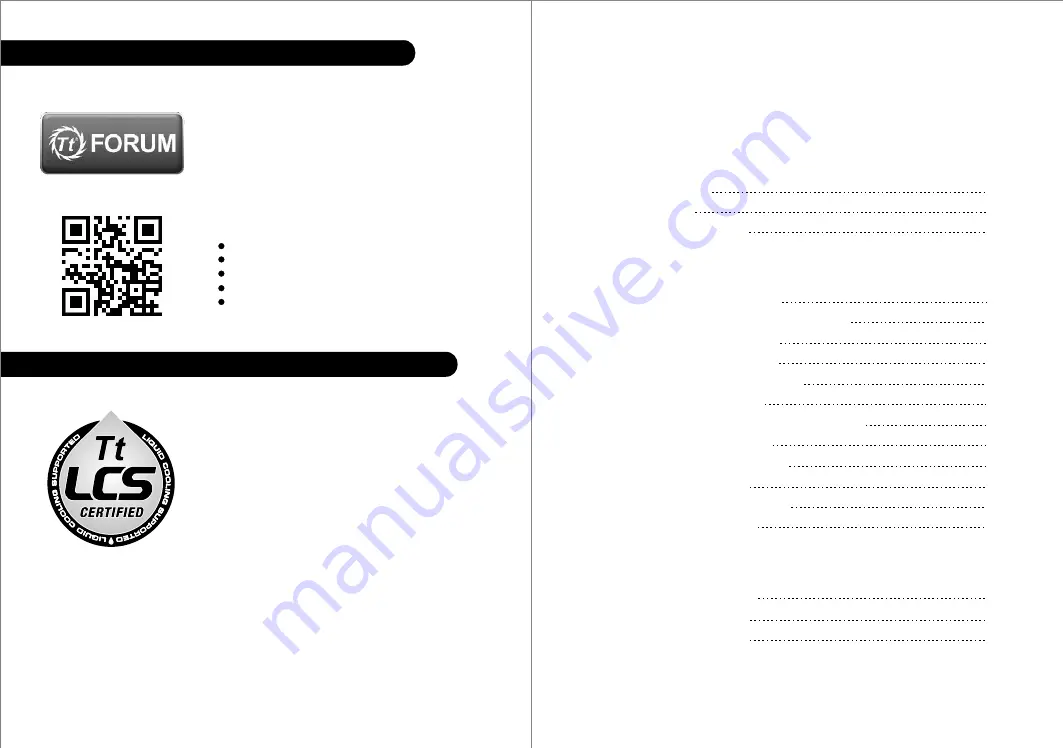
Join Tt Community To Receive Benefits

Tt LCS-Liquid Cooling Support Certification

Dear Valued Customer,
Thank you for choosing Thermaltake.
As a new user we value your thoughts and opinions and 
your feedback is important to us. We at Thermaltake 
would like to use this opportunity to invite you to join our 
Community Forums. Register today to start enjoying the 
full benefits of our community.

Benefits of being a member:
    Quick and responsive user support
    Receive help and advice with new builds
    Keep up to date with new product releases
    Share your thoughts and builds with the community
    Enter monthly contests and giveaways

Tt LCS Certified is a Thermaltake exclusive certification 
applied to only products that pass the design and 
hardcore enthusiasts standards that a true LCS chassis 
should be held to. The Tt LCS certification was created 
so that we at Thermaltake can designate to all power 
users which chassis have been tested to be best 
compatible with extreme liquid cooling configurations to 
ensure you get the best performance from the best 
features and fitment.

Brand official website

http://www.thermaltake.com/

Global Facebook

https://www.facebook.com/ThermaltakeInc

Taiwan Facebook 

http://www.facebook.com/ThermaltakeTW

Global community forums

http://community.thermaltake.com

藍色線條為尺寸標示,請勿印刷上去!

產 品 料號

CA-1D 8-0 0F1WN-00

Cor e X 9

說明 書

14

/

11

/

0 7

A

產品 名稱

印刷 項目

發稿 日 期

版 本

騎馬釘

28

105

G

雙銅

單色

其他特殊處理效果

表面處理

2

厚度

(g/m )

裝訂方式

材質

頁數

印刷色彩

規格樣式

整本

CHECK

DESIGN

刀模線

125

 mm

176

 mm

Peipei

(14/11/07)

Mike.Lin

(14/11/07)

Summary of Contents for Core X9 - A-2014.11

Page 1: ...Utilizador 安裝說明書 用戶手冊 ユーザーズマニュアル Руководство пользователя kullanıcı elkitabı EEE Yönetmeliğine Uygundur คู มือการใช 2014 Thermaltake Technology Co Ltd All Rights Reserved A 2014 11 All other registered trademarks belong to their respective companies www thermaltake com Tested To Comply With FCC Standards FOR HOME OR OFFICE USE Core 9 ...

Page 2: ...tant to us We at Thermaltake would like to use this opportunity to invite you to join our Community Forums Register today to start enjoying the full benefits of our community Benefits of being a member Quick and responsive user support Receive help and advice with new builds Keep up to date with new product releases Share your thoughts and builds with the community Enter monthly contests and givea...

Page 3: ...ce Warning and Notice 250 mm 400 mm Warning CPU Cooler Height Limitation Please ensure that your CPU cooler does NOT exceed 250mm 9 8 inches height VGA Add on card Length Limitation Please ensure that your VGA Add on card does NOT exceed 400mm 15 7 inches length Warnung CPU Kühler Höhenbeschränkung Bitte stellen Sie sicher dass Ihr CPU Kühler 250 mm 9 8 Zoll Höhe nicht überschreitet VGA Add on Kar...

Page 4: ...primento para VGA placa gráfica O limite de comprimento para VGA placa gráfica é 400 mm 15 7 polegadas 警告 警告 警告 Внимание Uyarı คำเตือน ขีดจำกัดความสูงสำหรับฮีตซิงก ของ CPU ขีดจำกัดความสูงสำหรับฮีตซิงก ของ CPU คือ 250 มม 9 8 นิ ว ขีดจำกัดความยาวสำหรับ VGA การ ดแสดงผล ขีดจำกัดความยาวสำหรับ VGA การ ดแสดงผล คือ 400 มม 15 7 นิ ว Side Panels Disassembly English Remove the screws on the back of the chass...

Page 5: ...ния и закреп ите блок питания винтами Türkçe 1 將電源供應器放在正確的位置 2 將電源供應器支撐架調整到適當的位置 然後用螺絲 固定電源供應器 1 将电源供应器放在正确的位置 2 将电源供应器支撑架调整到适当的位置 然后用螺丝 固定电源供应器 1 PSUを適切なロケーションに取り付けます 2 PSU支持ブリッジを適切なロケーションに合うよう に調整し ねじでPSUを締め付けます 1 PSU yu uygun konuma yerleştirin 2 PSU destek köprüsünü uygun konuma ayarlayın ve PSU yu vidalarla sabitleyin ภาษาไทย 1 วาง PSU ในตำแหน งที เหมาะสม 2 ขยับบริดจ ที รองรับ PSU ให อยู ในตำ...

Page 6: ...o dell unità per bloccare il dispositivo Nota Premere il meccanismo tool free da 5 25 per sbloccare il dispositivo Português 1 Puxe o painel dianteiro para fora 2 Remova a cobertura da baía da unidade de 5 25 3 Deslize o dispositivo de 5 25 para a baía da unidade para bloquear o dispositivo Nota Pressione o mecanismo de 5 25 sem utilizar ferramentas para desbloquear o dispositivo 繁體中文 1 拉面板底部 將面板從...

Page 7: ...y Installation With HDD Tray Type C2 M B Tray Installation Without HDD Tray For 2 5 HDD Secure 2 5 HDD from the bottom of the HDD by screws For 3 5 HDD Secure 3 5 HDD from both side of the HDD tray by locking clips For 2 5 HDD Secure 2 5 HDD from the bottom of the HDD by screws For 3 5 HDD Secure 3 5 HDD from both side of the HDD tray by locking clips Type A HDD Cage Installation Type B Center Pla...

Page 8: ...om inside of the chassis with screw Führen Sie die Kabel durch die Einheit Tastatur Maussperren und sichern Sie sie dann wieder an der Rückwand innerhalb des Gehäuses mit den Schrauben Mettez les câbles du clavier ou de la souris à travers le verrou de sécurité de clavier souris puis sécurisez les sur le panneau arrière à l intérieur du châssis avec des vis Mettez les câbles du clavier ou de la so...

Page 9: ...6 x 140mm 2 x 200mm Rear 2 x 120mm or 2 x 140mm Bottom 3 x 120mm Left Right Side 4 x 120mm 3 x 140mm Side Side Side Side Front 1 x 120mm or 1 x 240mm or 1 x 360mm 1 x 140mm or 1 x 280mm Top 2 x 120mm or 2 x 240mm or 2 x 360mm or 2 x 480mm 2 x 140mm or 2 x 280mm or 2 x 420mm Rear 1 x 120mm or 1 x 140mm Bottom 1x 120mm or 1 x 240mm or 1 x 360mm or 1 x 480mm 1 x 140mm or 1 x 280mm or 1 x 420mm Left R...

Page 10: ...15 16 Bracket Installation I O Panel Placement Guide Left Side Right Side 1 2 3 3 1 2 12cm 1 2 20cm A B Note ...

Page 11: ... Gehäuse LED Verbindungen Auf der Gehäusevorderseite finden Sie einige LEDs und Verbindungen Bitte nehmen Sie die Gebrauchsanweisung Ihres Motherboard Herstellers zur Hilfe und schließen Sie diese Verbindungen an die Panel Header Belegung des Motherboards an USB 3 0 Anschluss 1 Stellen Sie sicher dass Ihre Hauptplatine den USB 3 0 Anschluss unterstützt 2 Verbinden Sie das USB 3 0 Kabel mit dem USB...

Page 12: ... POWER MIC IN SENSE2 KEY SENSE1 PRESENSE GND L OUT R OUT MIC POWER MIC IN L RET KEY R RET GND Français Español USB 3 0 Connection L OUT SENSE R OUT MIC POWER MIC IN SENSE2 KEY SENSE1 PRESENSE GND L OUT R OUT MIC POWER MIC IN L RET KEY R RET GND Guida di installazione dei contatti Connessione del LED del case Nella parte anteriore del case sono presenti alcuni contatti per interruttori e LED Consul...

Page 13: ...D リード線の取り付けガイド ケース LED の接続 ケース前面には LEDとスイッチリード線があります マザーボードメーカーのユーザーマニュアル を参照し これらのリード線をマザーボードのパネルヘッダに接続してください USB 3 0 の接続 1 お使いのマザーボードがUSB 3 0接続をサポートしていることを確認してください 2 USB 3 0ケーブルをコンピュータの空いているUSB 3 0ポートに接続します オーディオ接続 オーディオコネクタの次の図とマザーボードのユーザーマニュアルを参照してください AC 97または HDオーディオ Azalia を使用するマザーボードを選択してください オーディオがAC 97またはHDオーディオ Azalia をサポ ートしていることを確認してください サポートしていないと デバイスが損傷します 日本語 Указания по прокладке...

Page 14: ...ayın aksi takdirde aygıt lar ınız zarar görür USB 3 0 Connection L OUT SENSE R OUT MIC POWER MIC IN SENSE2 KEY SENSE1 PRESENSE GND L OUT R OUT MIC POWER MIC IN L RET KEY R RET GND Türkçe คู มือการติดตั งสายไฟ การเชื อมต อไฟ LED ของเคส ที ด านหน าของเคส คุณจะเห นไฟ LED และสายไฟของสวิตซ กรุณาศึกษารายละเอียดจากคู มือผู ใช ของผู ผลิตแผงวงจรหลักของคุณ จากนั นให เชื อมต อสายไฟเหล านี เข ากับส วนหัวของแผ...

Reviews: