


33
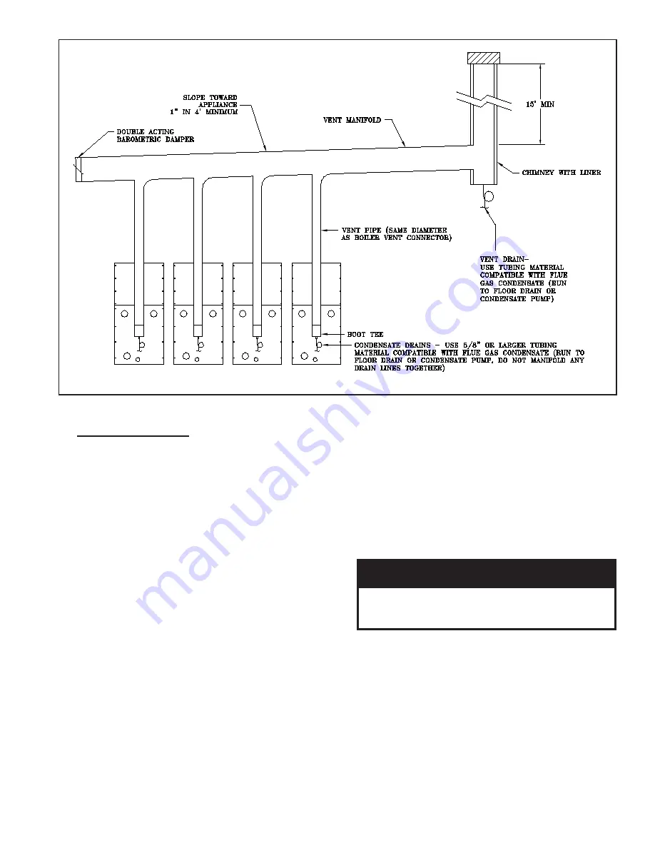
Figure 10: Modular System: Conventional Venting (Negative Pressure)
G
.
MODULAR SYSTEMS
1.
General Guidelines
a. Read and follow all venting, combustion
air, water piping, gas piping and electrical
instructions contained in this manual unless
otherwise instructed in this section.
b. Design and installation of modular systems
should only be undertaken by skilled and
knowledgeable engineers and contractors.
c. Consult Local Building Codes, National Fuel
Gas Code, or NFPA 54/ANSI Z223.1 for
restrictions and instructions for modular boilers.
d. Refer to the Pre-Installation section for further
warnings, cautions, notices and instructions.
2.
Module Sizing
Consult factory for recommended number and size
of boilers for a given input.
3.
Venting
This section outlines venting requirements for
multiple boiler installations and should be used in
addition to the “VENTING” section earlier in this
manual.
a. Positive Pressure (Sidewall and Vertical) Venting
i. Positive pressure vent systems cannot be
manifolded together.
ii. Positive pressure systems can be piped
individually through a common vertical
or horizontal chase provided minimum
clearances to combustible materials are
maintained.
iii. Positive pressure systems can be piped
individually through a common vertical
chase so that a single roof penetration can be
made. Each vent termination must be one (1)
foot from all other terminations.
WARNING
DO NOT manifold vent components of multiple
boilers without converting to a negative
pressure venting arrangement.
b. Negative Pressure (Conventional) Venting
i. Refer to Figure 10 for an example of a
typical conventional venting arrangement
for modular boilers.
ii. Refer to National Fuel Gas Code to
determine required chimney diameter
and common venting diameter. Note that
combined input, lateral length and chimney
height affect vent diameter.
iii. Install a double acting barometric damper
with integral flue spillage interlock (as
Summary of Contents for EVS SERIES
Page 14: ...14 Figure 4 Vertical Pressurized Venting ...
Page 16: ...16 Figure 5 Typical Negative Pressure Conventional Venting ...
Page 18: ...18 Figure 7 Vertical Air Intake Piping ...
Page 27: ...27 Figure 9a 208 230 460V 1 3 ph 60 Hz Supply Power Wiring Schematic ...
Page 28: ...28 Figure 9b 120V 1ph 60Hz Supply Power Wiring Schematic ...
Page 29: ...29 Figure 9c Standard UL FM CSD 1 Wiring Diagram EVS 500 2000 ...
Page 31: ...31 Figure 9e Standard UL FM CSD 1 EVS 2000S 3000 ...
Page 35: ...35 Figure 11 Modular System Horizontal Air Intake Piping ...
Page 36: ...36 Figure 12 Modular System Vertical Air Intake Piping ...
Page 37: ...37 Figure 13 Modular System Typical One Pipe Water Piping ...
Page 38: ...38 Figure 14 Modular System Typical Primary Secondary Water Piping ...
Page 39: ...39 Figure 15 Modular System Typical Primary Secondary without System Pump ...
Page 40: ...40 Figure 16 Modular System Typical Reverse Return Water Piping ...
Page 41: ...41 Figure 17 Modular System Reverse Return with System Pump Only ...
Page 42: ...42 Figure 18 Modular System Typical Primary Secondary with Reverse Return ...
Page 58: ...58 Figure 19 Combustion Chamber Assembly ...
Page 60: ...60 Figure 20 Burner Assembly FRONT VIEW TOP VIEW ...
Page 62: ...62 Figure 21 UL FM CSD 1 Main Gas Train Assembly ...
Page 65: ...65 Figure 22b DB B Gas Train 500 750 Figure 22c DB B Gas Train 1000 2000 ...
Page 70: ...70 Figure 23 Jacket Panels ...
Page 74: ...74 Figure 25 Pilot Assembly Bishop Design ...
Page 88: ...88 NOTES ...
Page 89: ...89 NOTES ...
Page 90: ...90 NOTES ...
Page 91: ...91 NOTES ...


