17
User Setup – Stage Order
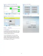
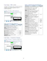
Compressor Stage Order Screen
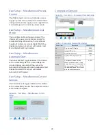
Figure 41
- Compressor Stage Order Screen depicts
the stage order of the local chiller. The stage order
calculation uses the hours entered in the auto-stage
threshold parameter. The intent is to run the
compressors with the least number of hours first to
help equalize the run hours of all the compressors
Figure 41 - User Setup – Stage Order Setup
Table 7 – Stage Order Setup Parameters
Menu Item
Description
Default Value
Stage Mode
Automatic: calculates the stage
order by the AUTO STAGE
THRESHOLD parameter
Manual: Manually enter the stage
order
AUTO
Auto Stage
Threshold
The number of run hours before
recalculating the stage order
24 HOURS
Minutes Until
Auto Stage
Minutes remaining until the stage
calculation occurs
N/A
User Setup – Discharge Control Setup
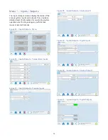
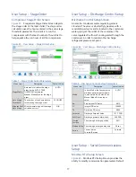
Discharge Control Setup Screen
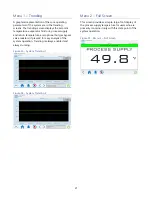
An electric condenser water-regulating valve is
standard. The valve is a butterfly type valve with a
modulating actuator and is located in the condenser
water piping at the outlet of the condenser. The
valve regulates the flow of cooling water through the
condenser in order to maintain the discharge
refrigerant pressure set point.
Figure 42 - User Setup – Discharge Control Setup
Table 8 – Discharge Control Setup Parameters
Menu Item
Description
Default Value
Mode
In Auto Mode, the fans adjust to
maintain optimum performance.
In manual mode, it holds to the
Manual Mode Position input
valve.
AUTO
Kp Proportional
PID
value
0.015
Ti Integral
PID
value
150.000
Td Derivative
PID
value
0.000
Setpoint
Discharge Setpoint Value
121.7 PSIG
Soft Limit
Discharge pressure alarm limit
240 PSIG
Startup
Position
The starting discharge position
50%
Startup delay The starting discharge delay time
30 sec.
Action
Control action
Forward/Reverse
Forward
User Setup – Serial Communications
Setup
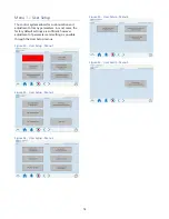
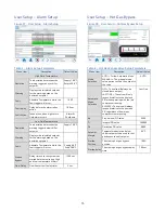
Modbus RTU Setup Screen
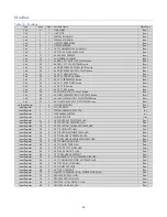
Figure 43
- Modbus RTU Setup Screen provides the
ability to modify communication parameters. Default


