background image

THERMAL INNOVATIONS (UK) LTD | THERMAFLOW® ELECTRIC COMBINATION BOILER | 

Tel: 0870 850 5207 


14

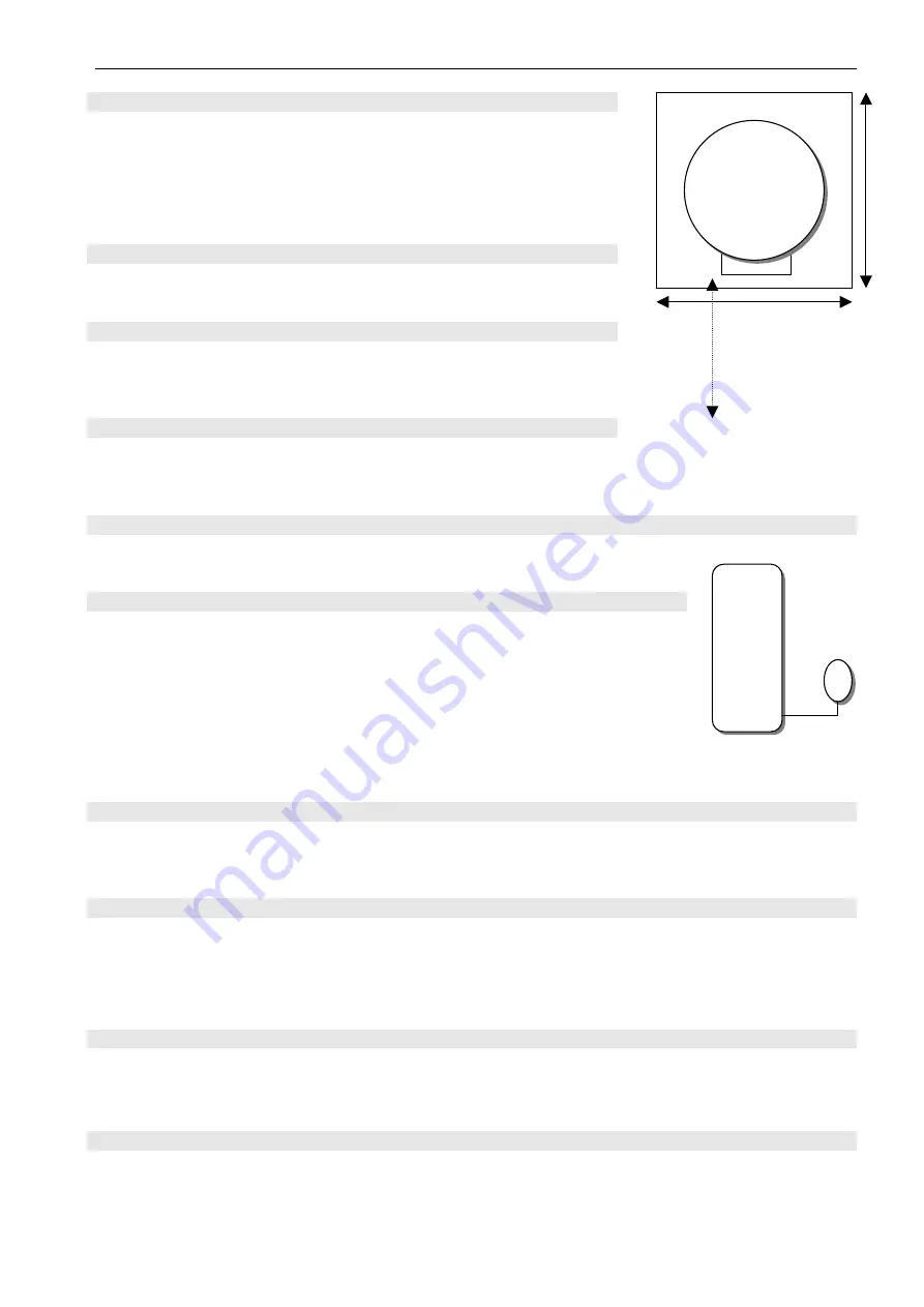
2.2.3 Clearances 


The boiler should be positioned so that at least the minimum 
operational and servicing clearances are provided, see diagram 
2.2.3 additional clearances may be required around the boiler for 
installation. A clearance of 600mm is required at the front of the 
boiler for maintenance and installation.


2.3.1 General notes 


The boiler is intended for use in a sealed system only. 


2.3.2 Safety valve  


The safety relief valve is an integral part of the boiler. It cannot 
be adjusted but has a manual test device. 


2.3.3 Pressure Gauge 


A pressure gauge is incorporated into the boiler to indicate the system pressure.  
The gauge has a cold fill set pointer. 


2.3.4 Pump 


The circulation pump is integral with the boiler. 


2.3.5 Expansion vessel 


The 

TSL9/140U & TSL12/140U,


TSL12/170 & TSL12/170U

 are all supplied 

with an expansion vessel with a capacity of 

25 

litres. If the system water 

content exceeds the maximum quoted in 

table 1

[Data]

 an additional vessel 

should be connected into the system as close as possible to the central 
heating return connection of the boiler. 

Ref. Di

agram 2.3.5


The charge pressure shall not be less than the static head at the point of 
connection, which is the height of the top point of the system above the expansion vessel. 


2.3.6 By- pass 


An automatic by- pass valve should be incorporated in the system for maximum system 
efficiency. (A By-Pass MUST be fitted on all models).  


2.3.7 Filling sealed systems 


The boiler has a filling loop incorporated within it, and pressure gauge to register the fill pressure. 


There must be no permanent connection to the mains water supply; even though a non return valve 
is supplied. 

Disconnect filling loop and seal both valves with suitable caps. 


2.3.8 Corrosion inhibitor 


The maintenance of sufficient concentration of corrosion inhibitor in your Thermaflow system is vital 
to prevent corrosion. We would recommend 

Sentinel X100, or equivalent

. Dose appropriately 

according to the size of the Thermaflow and central heating system volume combined.  

2.3.9 Draining 


A draining tap must be provided at the lowest points of the system, which will allow the 
entire system to be drained. The boiler has one drain tap fitted to it for the primary circuit. 


Thermaflow ®

Expansion
Vessel 


front 

Diagram 2.2.3

 - Clearances 

600mm 

Thermaflow 

Unit 

500mm

600mm

Diagram 2.3.5

Summary of Contents for TSL12/140U

Page 1: ...r guarantee and a second year parts guarantee In the instruction envelope is to be found your guarantee registration card which must be completed and returned to Thermal Innovations UK Ltd or register your Thermal Innovations UK Ltd appliance for 1st year guarantee protection by calling the below number Our guarantee gives you peace of mind valuable protection against breakdown by covering the cos...

Page 2: ...eral notes 14 2 3 2 Safety valve 14 2 3 3 Pressure Gauge 14 2 3 4 Pump 14 2 3 5 Expansion vessel 14 2 3 6 By pass 14 2 3 7 Filling sealed systems 14 2 3 8 Corrosion inhibitor 14 2 3 9 Draining 14 2 4 Domestic hot water system 15 2 4 1 General 15 2 4 2 Water pressure 15 2 4 3 HOT WATER FLOW RATE 15 2 4 4 Hard water areas 15 2 5 Installation PREPARATION water connections 15 2 5 1 Water connections 1...

Page 3: ...ol and high limit thermostats 29 Checking the elements 29 Checking circuit breakers 30 Checking the contactor 30 Check the operation of the AQUA STAT 30 Appendix I Solar Connection 31 A1 1 Solar Pipe work Schematic 31 A1 2 Solar Wiring Schematic 32 IMPORTANT PRE INSTALLATION NOTES Power supply and wiring The power supply to the premises must meet the minimum requirements of the unit being installe...

Page 4: ...ed power input of the appliance is 230 240V 50Hz 8 250 9 000w The TSL12 140U TSL12 170U all have 4 heating elements fitted Size 8 in length and are manufactured of Incaloy EN60335 2 73 The rated power input of the appliance is 230 240V 50Hz 11 000 12 000w The elements fitted to the Thermaflow should NOT be replaced with elements which have no thermal cut outs It is recommended that the Thermaflow ...

Page 5: ...iler is tested and certified for safety and performance It is therefore important that no alteration is made to the boiler without permission in writing from Thermal Innovations UK Ltd Any alteration not approved by Thermal Innovations UK Ltd could invalidate the certification boiler warranty and may also infringe the current issue of the statutory requirements see section 2 1 2 The unit should be...

Page 6: ...o be made when installing the Thermaflow they are as follows 1 Flow and return connections to the heating system are 22mm compression 2 Cold water inlet 22mm compression 3 Hot water outlet 22mm compression 4 Pressure relief valve 15mm compression 5 The pressure relief valve connection should be used for no other purpose ...

Page 7: ...3oC The combination boiler is able to provide room heating as part of an under floor or central heating system and domestic hot water direct from the cold water supply without the need for secondary storage 1 3 To turn the boiler off To turn the boiler off isolate the boiler from both the electrical supplies i e the 24hr supply and the interrupted supply both isolating switches should be positione...

Page 8: ... to do so Note if the pressure gauge indicates a loss of pressure that is less than 60 KPA 0 6 Bar YOU MUST CONTACT YOUR INSTALLER unless you have been instructed by your installer on how to re pressurise the system correctly 1 7 Replacement parts If replacements parts are required contact your Installer Service Company or Thermal Innovations UK Ltd Please quote the name and model of your applianc...

Page 9: ...l Heating Pump 8 Heating Elements 9 Aqua Thermostat 10 10 1 Enclosure for incoming live supply central heating pump Aqua stat 11 Heat Resistant Flex 12 0 5 Litre Potable expansion vessel 13 Thermostatic Blending Valve 13b HW outlet 15 Automatic Air Eliminator 15b connection for primary expansion vessel Blank off if connecting to CH Return 16 Stainless Steel Primary Store 17 17 1 Single check valve...

Page 10: ...harge 15mm Compression Water Content Primary 140 Litres 170 Litres Water Content Domestic 4 5 Litres 1 0 Gallons Primary Expansion Vessel 25 Litres 5 5 Gallons Heating Cold Fill Pressure Min Max 90 KPA 0 9 Bar minimum 120 KPA 1 2 Bar maximum D H W Working Pressure 20 400 KPA 0 2 4 0 Bar Max Heating system Content Excluding unit volume 140Litres 160Litres Electrical Mains Supply 230 240V 50Hz Elect...

Page 11: ...ower supply to the premises must meet the minimum requirements of the unit being installed with special attention given to the supply current cable size and MCB recommendation The supply voltage to the appliance must never drop below 207 Volts Important The electrical supply requirements The 9 KW and 12 KW boilers meet the requirements of EN 61000 3 3 The 9 KW and 12 KW boilers must be installed i...

Page 12: ...onal area of at least 10mm for the TSL9 model and 16mm for the TSL12 model The mains supply cable from the isolator to the boiler should be preferably encased by flexible conduit 2 1 6 Heating system controls The heating system should have installed A timer and room thermostat or a programmable room thermostat controlling the central heating system Thermostatic radiator valves should be installed ...

Page 13: ...easy removal of the boiler Where the boiler is fitted in a cupboard or compartment permanent ventilation is not required Compartment ventilation is required to dissipate heat from any external heating circuit pipe work to prevent overheating of the electrical components and wiring Any existing compartment air vents must not be removed or blocked off ...

Page 14: ...le to the central heating return connection of the boiler Ref Diagram 2 3 5 The charge pressure shall not be less than the static head at the point of connection which is the height of the top point of the system above the expansion vessel 2 3 6 By pass An automatic by pass valve should be incorporated in the system for maximum system efficiency A By Pass MUST be fitted on all models 2 3 7 Filling...

Page 15: ...nal advice A double check valve assembly must be fitted upstream of the scale reducer water softner for the relative position of the scale reducer water softner and pressure reducing valve if required refer to the manufacturers instructions 2 5 Installation PREPARATION water connections 2 5 1 Water connections See General Data Diagram 1 8 1 table 1 8 1 for pipe work connections It is recommended t...

Page 16: ...ower supply and wiring The power supply to the premises must meet the minimum requirements of the unit being installed with special attention given to the supply current cable size and MCB recommendation The supply voltage to the appliance must never drop below 207 Volts Important The electrical supply requirements The 9 KW and 12 KW boilers meet the requirements of EN 61000 3 3 The 9 KW and 12 KW...

Page 17: ... TO METER TELE SWITCH 100A Double Pole Isolating switch with 63A or 50A Type C MCB located at meter or consumer unit 100A Double Pole Isolating switch located adjacent to Thermaflow L N E THERMAFLOW TERMINALS Cable Sizing Boiler Rating Minimum Cable Size 230 240V 50Hz 8 250 9 000w 10mm and 11 000 12 000w 16mm MCB MUST BE RATED ACCORDINGLY AND BE TYPE C ...

Page 18: ...IC COMBINATION BOILER Tel 0870 850 5207 Diagram 2 6 2a 2 6 2 The mains supply into the enclosure marked No 10 1 on the boiler diagram should be wired to the 24HR supply via 3 Amp fused isolating switch located at the boiler ref diagram 2 6 2a 18 ...

Page 19: ...hould be connected to the terminals marked R1 R2 shown in diagram 2 6 2b All external controls should be connected to terminals marked R1 R2 in the enclosure marked No 22 in the boiler schematic diagram 1 8 1 WARNING ALL EXTERNAL CONTROLS MUST NOT BE TAKEN FROM ANY OTHER POWER SUPPLY OTHER THAN VIA THE 3 AMP FUSED ISOLATING SWITCH MENTIONED ABOVE 19 ...

Page 20: ...en and yellow Earth Make the earth cable of a greater length so that if the cable becomes strained the earth would be the last to become disconnected CAUTION IT IS ESSENTIAL TO MAKE SURE THAT THE POLARITY IS CORRECT 2 6 5 Heating system controls All external controls and wiring are required to provide a minimum of reinforced insulation at 250 vrms between the parts of those devices operating at ma...

Page 21: ...he enclosure cover Electricity tariffs The Thermaflow will operate on any 230 240V 50Hz supply The most economical option is a peak avoidance tariff as described previously Scottish Power Eastern Energy Guernsey Electric North Eastern Electricity all has an 18 hour tariff Other areas offer their own tariffs which may be viable for economic operation 2 7 Commissioning 2 7 1 Filling domestic water c...

Page 22: ...ng for central heating is 82oC this is the preset and is not adjustable 2 7 5 Heating system commissioning Make sure the boiler and heating system is completely full of water SEE ABOVE SECTION 7 2 Turn on both 24Hr Interrupted power supplies Allow approximately 90 160 minutes to bring the boiler up to temperature depending on model Check that all external controls are calling for heat Fully open a...

Page 23: ...d safe operation of the appliance it is recommended that it is checked and serviced at regular intervals The frequency of servicing will depend on the particular installation and usage but in general once a year should be enough Any servicing should be carried out by a person competent to do so Advise the user of the precautions necessary to prevent damage to the system and building in the event o...

Page 24: ...O TERMINALS ALL SUPPLY CIRCUITS MUST BE DISCONNECTED IMPORTANT ON COMPLETION OF THE FAULT FINDING TASK WHICH HAS REQUIRED THE BREAKING OR REMAKING OF THE ELECTRICAL CONNECTIONS THE CONTINUITY POLARITY SHORT CIRCUIT AND RESISTANCE TO EARTH CHECKS MUST BE REPEATED USING A SUITABLE MULTI METER Type of fault Check No domestic hot water or central heating 230 240V Supply 24HR 230 240V Supply Off Peak S...

Page 25: ...rect operation Yes Is there 230 240V at the off peak supply No Check Fuse or MCB Yes Is system pressure above 60 KPA 0 6 Bar No Increase Pressure Yes Is there continuity through master high limit stat No Replace Thermostat Yes Is there continuity through contactor No Replace Contactor Yes Is there 230 240V at each heating element and continuity through thermostats within No Replace or re set as ne...

Page 26: ...tats within No Yes Replace or re set as necessary Are external controls calling for heat No Yes Adjust the setting Is temperature above setting on aqua stat Should be set to 30o C No Yes Re check when temperature increases Check thermostat and lock shield Valves on radiators are open calling for heat Is there 230 240V and continuity at terminals of the aqua stat No Yes Check 230V Supply Is pump im...

Page 27: ...hot water at taps 27 Is the automatic air eliminator on top of the boiler in the open position causing an air trap in the top of the boiler No Open the small screw cap on top of the auto air eliminator Yes Is the hot water mixing valve set correctly No Set to desired temperature Yes Replace hot water mixing valve ...

Page 28: ...tect the blender from damage The pressure can be accurately checked with the pressure relieved on the other side of the diaphragm To do this isolate the water supply to the Thermaflow and open a hot tap Water will run for a few seconds then stop Connect a pressure gauge to the car tyre type valve on the vessel The pressure should register 100KPA 1 0 Bar on the 1 litre vessel or 350 KPA 3 5 Bar on ...

Page 29: ...U CAN PLACE THE THERMOSTATS IN A BEAKER OF COLD WATER AND THEN CHECK FOR CONTINUITY ACROSS THE THERMOSTAT CONTROL THERMOSTATS there are three or four of these thermostats in total one in each element The control thermostats are individually preset and sealed they should not be tampered with If a failure on one of the thermostats has occurred take note of which element it was removed from and conta...

Page 30: ...MCB s and in turn the heating elements Turn the main isolator on and off a few times and listen for this noise This will indicate correct operation of the contactor Check the operation of the AQUA STAT The Aqua Stat is positioned at the entrance to the pre heat coil on the cold water supply above the top heating element on the boiler Make sure the external controls are calling for heat Turn the di...

Page 31: ...THERMAL INNOVATIONS UK LTD THERMAFLOW ELECTRIC COMBINATION BOILER Tel 0870 850 5207 APPENDIX I SOLAR CONNECTION A1 1 Solar Pipe work Schematic 31 ...

Page 32: ...THERMAL INNOVATIONS UK LTD THERMAFLOW ELECTRIC COMBINATION BOILER Tel 0870 850 5207 A1 2 Solar Off Peak Wiring Schematic 32 ...

Reviews: