background image

1-877-420-1330 

Quest DRY 180                 Installation, Operation and Maintenance Instructions


7

www.QuestHydro.com

[email protected]

quest

quest

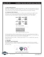
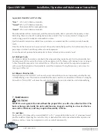
Approximate Humidity Levels Per Setting

“Drier”


35% to 45% Relative Humidity

“Normal”  45% to 55% Relative Humidity  

(Recommended for most applications)

“Humid”  55% to 65% Relative Humidity

The dehumidifier will run continuously until the relative humidity (RH) is reduced to the humidity control 
dial setting. There is no benefit to setting the humidity control to “dry” in rooms under 65°; doing so will 
result in long periods of ineffective dehumidifier run time.

Quality humidity meters are available from your dealer are recommended to accurately monitor humidity 
levels. 

Once the dial has been set to the desired level of humidity control, the Quest Dry 180 will maintain the same 
percentage of relative humidity regardless of room temperature.

To turn the unit off, position the humidity dial to the far left and set fan control to “auto.”

6.2 Defrost Cycle 

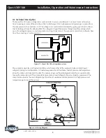
An automatic defrost thermostat is attached to the refrigerant tubes inside the unit. It will automatically shut 
the compressor off if excessive frost forms on the evaporator coil. The blower will continue to run, causing air 
to flow through the evaporator coil and melt the ice. When the ice has melted, the evaporator temperature 
will rise and the thermostat will automatically restart the compressor. During this process, cool air may be 
coming out of the unit.


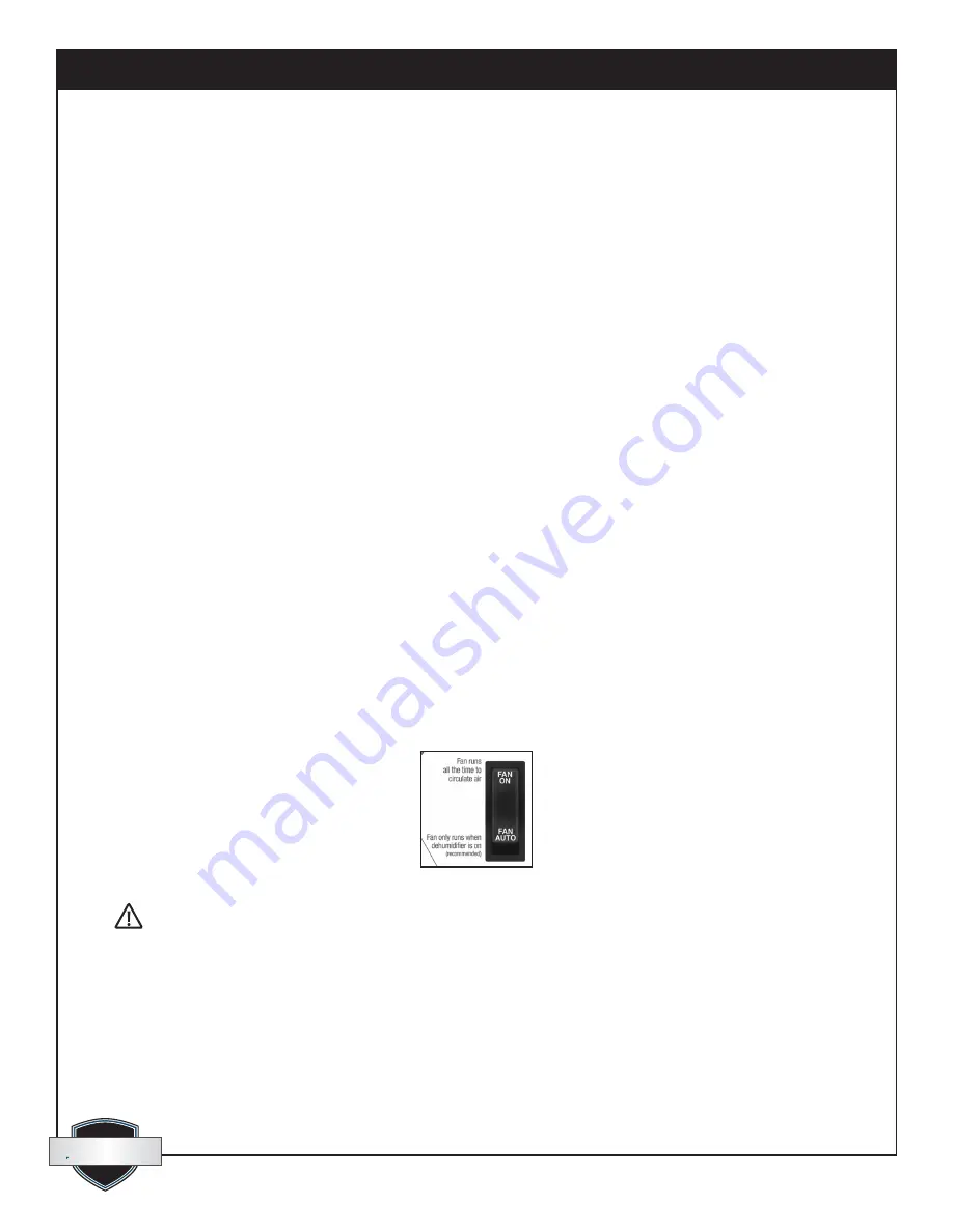
6.3 Blower (Fan) Switch 

Turning the fan switch “FAN ON” will cause the unit’s internal blower to run continuously, whether the unit 
is dehumidifying or not. This function is desirable if the unit is used for air circulation or filtration. Turning the 
fan switch to “FAN AUTO” will cause the unit’s internal blower to run only while the unit is dehumidifying.


7. Maintenance


NOTE: Do not operate the unit without the proper filter or with a less effective filter. The 
heat exchange coils inside the unit could become clogged, resulting in a loss of effective-
ness and/or efficiency and may require disassembly to clean.

7.1 Air Filter 

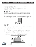
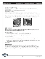
The Quest Dry 180 ships with a standard MERV-11 65% 1” pleated fabric filter and a 1/4” aluminum framed 
pre-filter installed. Operating the unit with a dirty or obstructed filter will reduce dehumidifier capacity and 
efficiency and may cause the compressor to cycle on and off unnecessarily. 

 CAUTION!


Summary of Contents for Quest DRY 180

Page 1: ...workmanship and function Quest DRY90 Installation Operation and Maintenance Instructions 4201 Lien Rd Phone 608 237 8400 Madison WI 53704 Toll Free 1 877 420 1330 www QuestHydro com Info QuestHydro com Read and Save These Instructions Specifications subject to change without notice TS 832 05 13 1 Quest DRY180 Water Removal Rates Pints Day 90 pints 80 F 60 AHAM 180 pints 86 F 80 Quest DRY 180 Uses ...

Page 2: ... 2 Attaching Drain Hose 5 5 Installation 5 5 1 Location 5 5 2 Electrical Requirements 6 5 3 Condensate Water Removal 6 6 Operation 6 6 1 Humidity Control Adjustment 6 6 2 Defrost Cycle 7 6 3 Blower Fan Switch 7 7 Maintenance 7 7 1 Air Filter 7 7 2 Cleaning and Replacement 8 7 3 Removing Filters 8 7 4 Installing Filters 8 8 Service 8 8 1 Technical Description 9 8 2 Troubleshooting 10 9 Optional Acc...

Page 3: ...RS IN A SPACE THAT IS PROTECTED FROM RAIN AND FLOODING Install the unit with space to access the back or side panels for maintenance and service DO NOT INSTALL UNIT WITH THE SERVICE PANELS INACCESSIBLE Avoid directing the discharge air at people or over the water in pool areas If used near a pool or spa be certain there is NO chance the unit could fall into the water be splashed and that it is plu...

Page 4: ...lectrical 110 120 VAC 6 7 Amps 60 Hz grounded Water Removal Capacity 90 pints day 80 F 60 RH Operating Temp Range 33 F min 110 F max Air Flow 220 CFM Refrigerant Charge 1 lb R410A Filter Size 12 X 12 X 1 Size 34 L X 14 1 2 W X 19 1 2 H Unit Weight 67 lbs Shipping Weight 73 lbs 4 Unit Assembly 4 1 Installing Feet Optional Included with your Quest Dry 180 are four leveling feet It is important to le...

Page 5: ...he Quest Dry 180 can be installed in a variety oflocations to meet the owner s needs but should beinstalled directly in the area to be dehumidified Other considerations include 1 Providing access to a 115 VAC power outlet 8 power cord is provided 2 Locating near a floor or other suitable drain 8 drain hose included 3 Do not install the Quest Dry 180 with the intake or exhaust of the unit within 1 ...

Page 6: ...o that water can pass through it Improper hose installation may result in water leakage To increase the efficiency of the unit position the hose to create a trap as shown in Figure 8 By creating a trap it will hold a small amount of water Position the trap on the hose approximately 12 to 20 away from the unit Check hose regularly to ensure it is clear and water is draining properly If floor drain ...

Page 7: ...ically shut the compressor off if excessive frost forms on the evaporator coil The blower will continue to run causing air to flow through the evaporator coil and melt the ice When the ice has melted the evaporator temperature will rise and the thermostat will automatically restart the compressor During this process cool air may be coming out of the unit 6 3 Blower Fan Switch Turning the fan switc...

Page 8: ...ructions below or on the tag located on the 1 4 pre filter NOTE Failure to follow filter handling instructions may result in improper function of the dehumidifier and cause premature filter wear 7 3 Remove Filters 1 Gently remove the 1 4 pre filter by pulling on the tab attached to the filter 2 Gently remove the 1 pleated fabric filter by pulling it out of the unit 7 4 Installing Filters 1 Gently ...

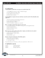
Page 9: ...use the refrigerant pressure and temperature to drop It next enters the evaporator coil where it absorbs heat from the incoming air and evaporates The evaporator operates in a flooded condition which means that all the evaporator tubes contain liquid refrigerant during normal operation A flooded evaporator should maintain constant pressure and temperature across the entire coil from inlet to outle...

Page 10: ...mpressor or compressor run capacitor Blower runs with fan switch AUTO but compressor cycles on off 1 Low ambient temperature and or humidity causing unit to cycle through defrost mode 2 Defrost thermostat defective 3 Defective compressor overload 4 Defective compressor Blower does not run with fan switch in either position Compressor runs briefly but cycles on and off 1 Loose connection in blower ...

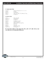
Page 11: ...b 4025577 Hose PVC Clear 625 diameter 8 long 4026221 Leveling Feet 9 2 Service Parts 4025561 Blower Assembly 4034147 02 Coil Assembly 4029168 Compressor 4029169 Compressor Overload 4025741 Defrost Thermostat 4021648 Defrost Control Mounting Clip 4025560 Fan Switch 4029510 Filter Drier 4021469 Humidity Controller 4033032 05 Run Capacitor For more information on the Quest Dry 180 call 1 877 420 1330...

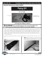
Page 12: ...umidifier or another automatic cut off device Only a certi fied electrician is qualified to connect the safety trip wires to your Therma Stor dehumidifier Attaching the overflow safety trip wires to your Therma Stor dehumidifier will cut power to the dehumidifier if the pump motor should fail and the secondary float switch trips this process is optional and not necessary on every install You may a...

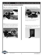
Page 13: ...as removed in step 2 Step 4 Remove the 7 hose from the plastic bag and install this hose from the condensate pump onto the adaptor as indicated Make sure that the hose fully covers the adaptor barbs on the unit Step 5 Attach the 20 drain hose to the condensate pump and route it to a floor drain Note Do not exceed 10 feet vertically when pumping to a drain above the unit Step 6 Plug the pump and de...

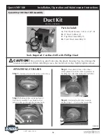
Page 14: ...ith Phillips Head Duct Kit Part No 4026055 OVER Parts Included A Pan Head Screws 10 16 x 1 2 8 B 8 Duct Collars 2 C Top Duct Assembly 1 D Front Duct Assembly 1 B C D A ATTACHING COLLARS Step 1 Position collar on a flat surface with tabs up Step 2 Position collar into large hole of front duct assembly Press firmly so that tabs of collar go through the plenum hole Step 3 Press down firmly on the she...

Page 15: ...o strip loose Lightly tighten screws Do this in all four through hole locations TOP DUCT ASSEMBLY Step 1 Check sealing foam on the top duct assembly Ensure none has come loose Step 2 Place top duct assembly ensure the sealing foam makes contact around the plastic surfaces Step 3 Center the top duct assembly ensure the sealing foam makes contact around the plastic surfaces Step 4 Ensure the rear fl...

Page 16: ...and reliable means The end user is responsible for normal care This warranty only applies to residential applications and does not cover any defect malfunction etc resulting from misuse abuse lack of normal care corrosion freezing tampering modification unauthorized or improper repair or installation accident acts of nature or any other cause beyond Therma Stor LLC s reasonable control LIMITATIONS...

Reviews: