background image

Posi�on the stay bar connectors central 

to the markings. With a small drill bit 

mark the holes for drilling.

Use masking tape on the �les to mark.

10

Using a 5mm high quality drill bit for a 

clean and precise hole, drill the marked 

areas, fully insert the wall plugs and fix 

the connectors to the wall.

11

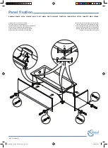
Carefully replace the panel by lowering 

onto the spacers.


Remember the glass must be inline 

with the channel ends.

12        

13

Place the glass clamp over the glass 

using the screw and white plas�c 

washer provided.

A�ach the stay bar to the wall 

connector with grub screws provided.

05/06

Professional Tip

If drilling ceramic tiles, place 

masking tape on the tiles before 

marking and drill through the 

tape to prevent the drill bit from 

skidding.

DO NOT use Hammer Action as 

this will break the tiles.

Flush

Shower Tray

Channel

Glass Panel

VIEW 20

07/2019  V 2.2

Summary of Contents for VIEW 20

Page 1: ...Illustration View 20 VIEW 20 07 2019 V 2 2...

Page 2: ...glass is moved to its final position Ensure that the glass is installed correctly taking care to avoid installing the glass upside down On certain panels an easy clean coating is applied to one side...

Page 3: ...Supplied Parts Glass Panel x1 Surface Channel x1 SB6 Stay Bar x2 1mm Spacer x2 3mm Spacer x2 End Cap x2 VIEW 20 07 2019 V 2 2...

Page 4: ...ure The image below shows the screen with two SB6 stay bars connecting to the opposite wall Please use the below diagram to reference the list of parts A B C D E Glass Panel Surface Channel SB6 Stay B...

Page 5: ...E D SCALE REV 1 4 3mm minimum Outside of shower Inside of shower Wet Side Shower Tray 01 06 Using purpose made Glass Li ers squarely insert and lower the panel onto the spacers Take great care NOT to...

Page 6: ...X Align the panel so it is inline with the ends of the channel Flush Shower Tray Channel Glass Panel Using a spirit level align the panel so it is ver cal Check the top edge is level This can be achie...

Page 7: ...unior hacksaw and ne le to cut and nish the edge DO NOT discard the o cut A B SB6 Stay Bar Configuration Take 6mm o this measurement Mark the nal dimension on the stay bar tube wrapped with some maski...

Page 8: ...f the stay bar tube Ensure the staybars are square and level Mark the end loca ons on the wall Remove the Stay bars and the main panel C D 8 9 SB6 Stay Bar Configuration Assemble the glass clamps to t...

Page 9: ...el by lowering onto the spacers Remember the glass must be inline with the channel ends 12 13 Place the glass clamp over the glass using the screw and white plas c washer provided A ach the stay bar t...

Page 10: ...cone sealant as shown below to where the glass meets the surface channels and where the channels meet the oor This screen is NOT water ght unless this step is followed 15 Allow the whole enclosure to...

Reviews: