background image

Greenlee / A Textron Company

2

4455 Boeing Dr. • Rockford, IL 61109-2988 USA • 815-397-7070

1990 Hydraulic Crimping Tool

Table of Contents

Description ..................................................................... 2

Safety ............................................................................. 2

Purpose of this Manual .................................................. 2

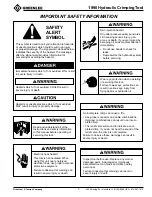
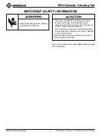
Important Safety Instructions ...................................... 3-4

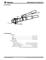
Identification ................................................................... 5

Specifications ................................................................. 5

Operation .................................................................... 6-7

cUL and UL Classified Crimps ....................................... 8

Periodic Pressure Relief Valve Check ........................... 9

Maintenance .................................................................. 9

Troubleshooting ........................................................... 10

Air Purging and Oil Filling Procedure .......................... 11

Exploded View ............................................................. 12

Parts List ...................................................................... 13

Description

The 1990 Hydraulic Crimping Tool is a hand-held, self-
contained dieless crimping tool intended to crimp
aluminum and copper connectors onto electrical cable.

The hinged crimping head, which allows easy loading
and unloading of splice connections, swivels 180

°

 for

maximum flexibility. The two-speed hydraulic system
automatically switches from rapid advance (for quick
snug-up) to normal advance (to accomplish the crimp).
An internal pressure regulating system automatically
sets the correct pressure for the connector.

This tool is cUL and UL classified for use as directed on
the cUL/UL Table provided in this manual and on the
carrying case.

The 1990 Crimping Tool is protected by US Patent No.
4,796,461.

Safety

Safety is essential in the use and maintenance of
Greenlee tools and equipment. This manual and any
markings on the tool provide information for avoiding
hazards and unsafe practices related to the use of this
tool. Observe all of the safety information provided.

Purpose of this Manual

This instruction manual is intended to familiarize all
personnel with the safe operation of the Greenlee 1990
Hydraulic Crimping Tool.

Keep this manual available to all personnel.

Replacement manuals are available upon request at no
charge.

KEEP THIS  MANUAL

All specifications are nominal and may change as design improve-
ments occur. Greenlee Textron shall not be liable for damages
resulting from misapplication or misuse of its products.

Blackburn is a registered trademark of Thomas & Betts Corporation.

Dow Corning is a registered trademark of Dow Corning Corporation.
RTV Sealant 732 is a trademark of Dow Corning Corporation.

UL is a registered trademark of Underwriter’s Laboratories,
Incorporated.

UNIVIS is a registered trademark of Exxon Corporation.

Summary of Contents for Greenlee 1990

Page 1: ... 999 9994 3 2003 Greenlee Textron IM 1093 REV 8 5 03 Read and understand all of the instructions and safety information in this manual before operating or servicing this tool 1990 Hydraulic Crimping Tool Serial Code YM ...

Page 2: ...d for use as directed on the cUL UL Table provided in this manual and on the carrying case The 1990 Crimping Tool is protected by US Patent No 4 796 461 Safety Safety is essential in the use and maintenance of Greenlee tools and equipment This manual and any markings on the tool provide information for avoiding hazards and unsafe practices related to the use of this tool Observe all of the safety ...

Page 3: ...y or death Wear eye protection when operating or servicing this tool Failure to wear eye protection can result in serious eye injury from flying debris or hydraulic oil Skin injection hazard Oil under pressure easily punctures skin causing serious injury gan grene or death If you are injured by escaping oil seek medical attention immediately Do not use hands to check for leaks Depressurize the hyd...

Page 4: ... away from the crimping tool head when crimping This tool is intended for two handed operation Maintain a firm grip on both handles during operation Using this tool in any other manner can result in injury or property damage Do not perform any service or maintenance other than as described in this manual Injury or damage to the tool may result Failure to observe these precautions can result in inj...

Page 5: ...dth 26 3 mm 2 87 Mass Weight 7 5 kg 16 5 lb Hydraulic Oil 198 cc 12 in3 Crimping Capacities Crimping Range Copper Connectors 25 500 mm2 4 AWG 1000 kcmil Aluminum Connectors 16 500 mm2 6 AWG 1000 kcmil Maximum Crimper Diameter 461 mm 1 815 Crimping Force maximum 133 kN 15 tons Crimping Tool Adjusts Automatically to Connector Size MOVABLE PIN UNIT RELEASE TRIGGER RAM DIE DIE HEAD ...

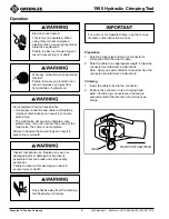
Page 6: ...nt Failure to observe this warning can result in severe injury or death Wear eye protection when operating this tool Failure to wear eye protection can result in serious eye injury from flying debris or hydraulic oil Inspect tool before use Replace any worn or damaged parts A damaged or improperly assembled tool can break and strike nearby personnel Failure to observe this warning can result in se...

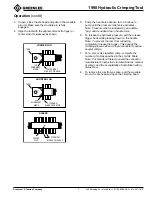
Page 7: ...e release trigger back while pressing down on the handle Note To prevent the ram from retracting completely release the trigger This speeds the crimping process when a single connector requires several crimps 7 For a cUL or UL classified crimp complete the number of crimps specified in the cUL UL Table Note For brands not listed consult the connector manufacturer s instructions to determine the nu...

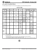
Page 8: ... L A Y C T L A Y B R C A R C L B R C L A R C L 2 A R C L 2 B R C 8 2 1 4 5 6 0 1 4 5 8 2 2 4 5 6 0 2 4 5 8 2 9 4 5 6 0 9 4 5 2 8 8 4 5 4 5 8 4 5 U L B U L B B m u n i m u l A n i P r o t c e n n o C P E C P Y A M C A G W A 6 l i m c k 0 0 0 1 L A P T G W A 6 l i m c k 0 5 7 m u n i m u l A 1 m u n i m u l A t e s f f O r o t c e n n o C O P E C O P Y A O C A G W A 6 l i m c k 0 0 0 1 L A O P T G W...

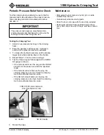
Page 9: ... as shown If the GO slot will fit over the slug and the NO GO slot will not the pressure is within the specified range If the GO slot will not slide over the slug the crimping pressure is too low Send the crimping tool to an authorized service center If the NO GO slot will slide over the slug the crimping pressure is too high Send the crimping tool to an authorized service center The pressure test...

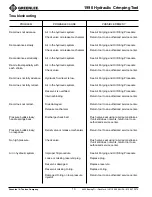
Page 10: ...ully retract Air in the hydraulic system See Air Purging and Oil Filling Procedure Reservoir is overfilled See Air Purging and Oil Filling Procedure Internal binding Return tool to an authorized service center Ram does not retract Dies damaged Return tool to an authorized service center Release mechanism Return tool to an authorized service center Pressure builds slowly Discharge check ball Flush ...

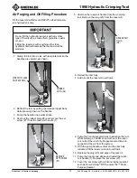
Page 11: ...ty 8 Pump the handle several times to advance the ram While holding a CLEAN shop cloth over the reser voir retract the ram fully Repeat several times to purge all of the air from the system 9 With the pump handle vertical and the ram fully retracted fill the reservoir until it overflows 10 Replace the plug 25 and wipe off excess oil 11 Pump the handle one stroke and install the reser voir handle 1...

Page 12: ...eing Dr Rockford IL 61109 2988 USA 815 397 7070 1990 Hydraulic Crimping Tool Exploded View 7 17 29 5 4 2 3 23 24 25 22 16 21 27 26 1 18 19 20 28 15 16 14 13 10 11 12 8 15 6 9 24 Torque cap screws 13 to 20 3 Newton meters 15 foot pounds 1 1 ...

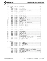
Page 13: ... 2 16 51379 905 1379 7 Ring Retaining 500 Truarc 2 17 32514 503 2514 0 Die Ram 1 18 35677 503 5677 1 Head Die 1 19 53962 905 3962 1 Detent Ball 1 20 52338 905 2338 5 Screw Set 10 32 x 250 Socket 1 21 35678 503 5678 0 Pin Unit Movable 1 22 35673 503 5673 9 Pin Pivot 468 x 2 05 1 23 53814 905 3814 5 O ring 1 47 x 1 71 x 118 1 24 35686 503 5686 0 Reservoir 1 25 32488 503 2488 8 Plug Rubber Reservoir ...

Page 14: ... 397 7070 Fax 815 397 1865 Canada 800 435 0786 Fax 800 524 2853 International 1 815 397 7070 Fax 1 815 397 9247 4455 Boeing Drive Rockford IL 61109 2988 USA 815 397 7070 An ISO 9001 Company Greenlee Textron is a subsidiary of Textron Inc www greenlee com ...

Reviews: