Texmate, Inc. Tel. (760) 598-9899 • www.texmate.com
DL-40JANUS-DCA/DCV manual (d0114)
Page 5
When the rear Auto/Manual switch is in the Auto position, the meter can be calibrated with an automatic scale factor calculation,
by applying a low input signal (InLo), entering the desired low display reading for that signal (ZERO), then applying a high input
signal (InHi), and then entering the desired high display reading (SPAN). The meter then automatically calculates and programs in
the requisite scale factor using a true linear (y=mx + b) calculation where m = (SPAN-ZERO)/(InHi-InLo) and b = ZERO, but within
the following parameters.
1. Positive and negative signals may be applied, but the difference between the high and the low signal inputs must be at least 1000
counts or Err will be indicated.
2. Positive and Negative values for the desired reading can be entered, but the scale factor created can not exceed the Digital
Display Span capability of the meter which is 12,000 counts between –1999 to 9999.
3. The internal Signal Span is limited to 3 V DC between – 1 V DC to + 2 V DC. Any outputs from an Input Signal Conditioning
module that exceed these limits will cause the meter to indicate overrange regardless of the Digital Display Span scaled.
Note: Most input signal conditioners have provisions for analog calibration and scaling. If the meter’s digital scale factor is set to
read zero with a zero input (shorted input), and to read 1000 with a 1.000 V input, any pre-calibrated signal conditioner with an
output that does not exceed – 1 V to + 2 V, will read correctly in the meter without any further calibration.
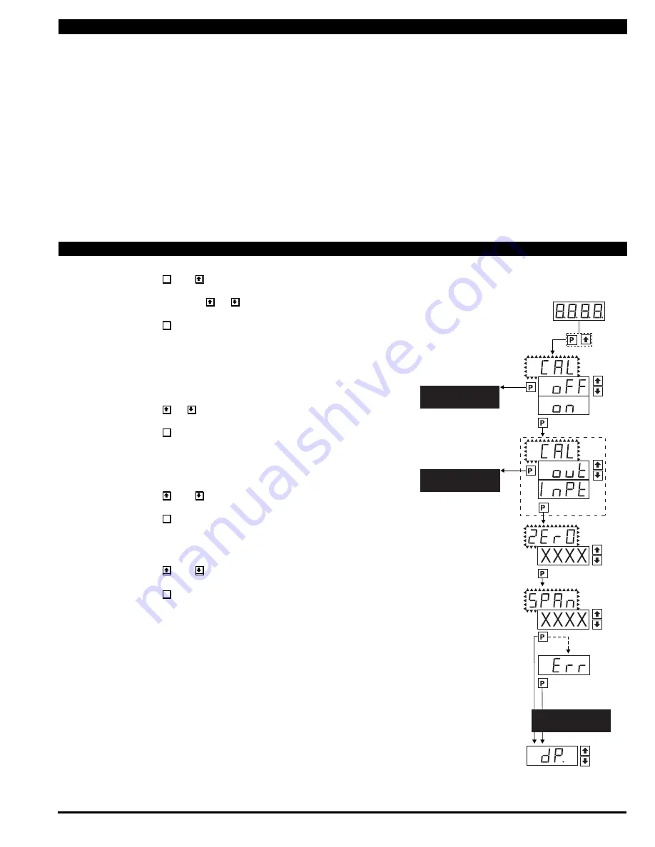
STEP A Enter the Calibration Mode
1) Press the
P
and buttons at the same time.
Display toggles between [CAL] and [oFF].
2) Press and hold the or button.
Display changes from [oFF] to [on].
3) Press the
P
button. Display toggles between [ZErO] and the
previous zero setting.
STEP B Select Between Two Point Digital Calibration of Input Signal and
Two Point Analog Output
Note: If the analog output option is not present, Step B is skipped and the
program goes directly from Step A to Step C.
1) Press the or button to select the display toggling from [CAL]
to [inPt] input calibration.
2) Press the
P
button. Display toggles between [ZErO] and the
previous zero setting.
STEP C Set the Meter’s Low Input Signal Reading on the Digital Display
1) Apply a zero or low signal to the meter.
(Positive or negative values are allowed)
2) Using the and buttons, adjust the meter display to the
desired reading for the applied low input signal.
3) Press the
P
button. Display toggles between [SPAn] and the
previous span setting.
STEP D Set the Meter’s High Input Signal Reading on the Digital Display
1) Apply a high input signal to the meter.
2) Using the and buttons, adjust the digital display to the
desired reading for the applied high input signal.
3) Press the
P
button.
The Digital Calibration Procedure Mode is Now Complete.
If the digital calibration was successfully completed, the menu
branches to the DISPLAY FUNCTION CONFIGURATION MODE,
(see page 7) and the display flashes [dP] and the previous setting.
ERROR Indicates Unsuccessful Calibration
If the calibration was unsuccessful, the display indicates [Err],
the new calibration settings just entered will not take effect and
the previously stored setting will remain.
The three most likely causes of an error during calibration are:
1) The full scale and zero signals were too similar. The full scale
signal must be at least 1000 counts greater than the zero or
low input signal (positive and negative values are allowed).
2) The scaling requirement exceeded the capability of the meter
(–1999 to 9999).
3) No input signal present, or incorrect connections.
Auto Calibration Mode
Auto Calibration Procedure
MAIN MENU
Operational Display
Sub-menu
MODE
STEP A
Calibration
Mode
STEP B
Calibration
Mode
DECIMAL POINT AND
BRIGHTNESS SELECTION
See Page 6
STEP C
Zero
STEP D
Span
DECIMAL POINT AND
BRIGHTNESS SELECTION
See Page 6
Decimal Point
(dp)
Err. Any new setting
canceled and previous
settings are retained
TWO POINT ANALOG
OUTPUT CALIBRATION
SEE PAGE 6


