Texecom Premier Elite 8XP, Manual
The Texecom Premier Elite 8XP is a top-of-the-line security system designed for ultimate protection. Ensure you have all the information you need by downloading the free user manual from manualshive.com. This comprehensive manual covers installation, programming, and troubleshooting, giving you peace of mind.
Share
Download


Reviews:
No comments
Related manuals for Premier Elite 8XP
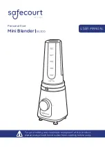
BL300
Brand: SafeCourt Pages: 21
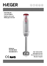
Extreme
Brand: HAEGER Pages: 20

N300RE
Brand: on networks Pages: 12

SBC-B16
Brand: Specialized Pages: 5

EPOC-POE-100K
Brand: AAS Pages: 8

USB-EXT-DM
Brand: Crestron Pages: 2

B15FM-120
Brand: Cecilware Pages: 2

XAUB2511
Brand: NETGEAR Pages: 27

TriForce JB 901AN
Brand: Braun Pages: 20

CE-VG0711-SA
Brand: SIIG Pages: 8

MyBlend PLUS
Brand: Oster Pages: 8

AO-CA70 Plus
Brand: Aobost Pages: 10

C5-SVA2
Brand: Niles Pages: 3

RHB-B41/B
Brand: Rasonic Pages: 46

E30
Brand: D-Link Pages: 77

CAD-HV-EX03
Brand: Cadenceberge Pages: 4

STI-32000
Brand: STI Pages: 2

VS-108R
Brand: Lanbe Pages: 5


