11
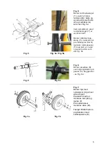
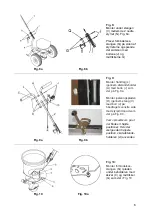
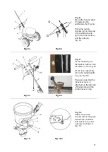
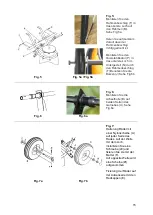
Fig. 8:
Mount the handle shaft
(V) between the
subframes (N). Fig. 8a.
Place the pivot &
bracket (Q) on the side
of the subframe and
tight it with the bolts (J)
and the nuts (G).
Fig. 8b
Fig. 8a
Fig. 8b
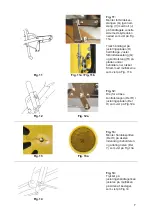
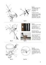
Fig. 9:
Fit the handles (L) to
the spacer bushes. Use
the bolts (J). See Fig.9a
Fit the lever assembly
(O) to the handle shaft
(V), see Fig. 9b..
Please ensure that the
dispenser lever is
attached on the left side
of the handle with the
control lever on top.
Fig. 9a
Fig. 9b
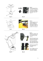
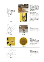
Fig. 10:
Attach the pivot &
bracket (Q) on the plate
beneith the container
with washers (C) and
nuts (G) as shown in
Fig. 10.
Fig. 10
Fig. 10a


