9
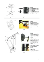
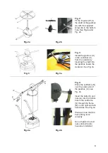
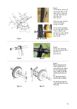
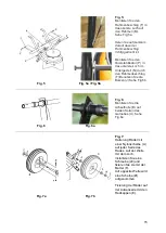
Fig. 2:
Fit the impeller (W) to
the shaft of the gearbox
(U) with the supplied
screw (D) in the bottom
hole. See Fig.2a and
Fig. 2b.
Fig. 2a
Fig. 2b
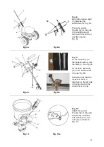
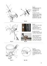
Fig. 3:
Install the gearbox (U)
in the container (X)
from the outside by
inserting the shaft into
the gearbox inside the
container. See Fig.3a
Fig. 3
Fig. 3a
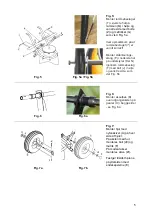
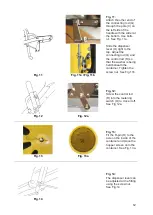
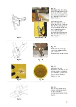
Fig. 4:
Place the subframe (N)
over the outer axle of
the gearbox (U), see
Fig. 4b
Insert the bolts (K) and
nuts (G) into the bottom
hole in the subframe
(N) through the frame
(M) on the right and left-
hand sides. See Fig.4a
Please ensure that the
frame fitting turns
correctly.
Do not tighten the bolt
nuts until both bolts
have been installed.
Fig. 4a
Fig. 4b


