www.ti.com
Board Layout
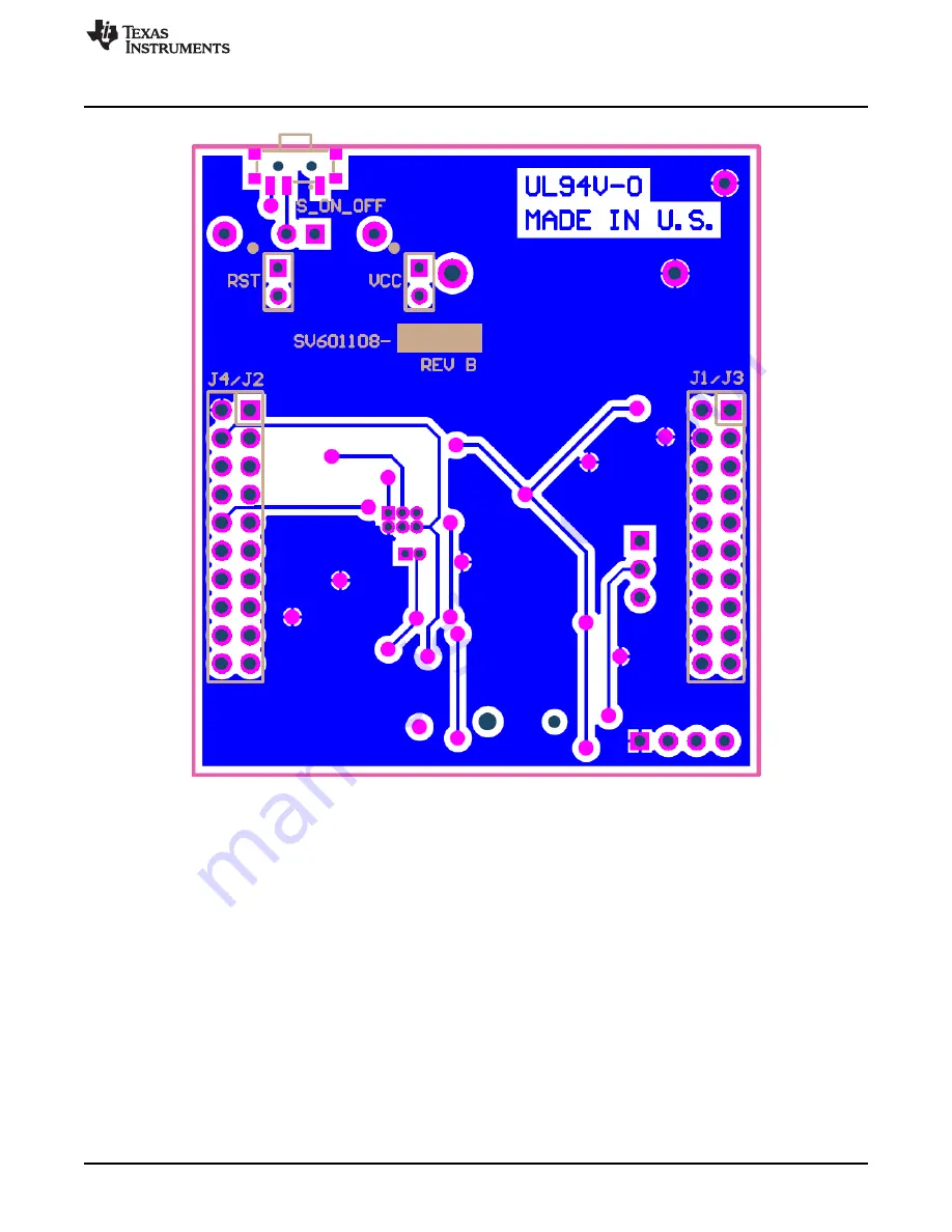
Figure 14. Bottom Layer
15
SNAU173 – January 2015
TPL5010 Evaluation Module
Submit Documentation Feedback
Copyright © 2015, Texas Instruments Incorporated
Page 1: ...mpers Configuration EVM Standalone Without Microcontroller 6 8 Jumpers Configuration EVM With Microcontroller 7 9 Jumpers Configuration EVM With LaunchPad 8 10 Current Measurement Setup TPL5010 Only 1...
Page 2: ...over the TPL5010EVM is ready to be connected to the LaunchPad of the MSP430F5529 in order to test its watchdog and timer features The EVM has an onboard battery holder coin battery to supply the TPL50...
Page 3: ...aunchPad RST Bottom 2 pin receptacle to plug the TPL5010EVM into the MSP430F5529 LaunchPad VCC Bottom 2 pin receptacle to plug the TPL5010EVM into the MSP430F5529 LaunchPad IO Top 4 pin header connect...
Page 4: ...Pin2 3 in short configuration the fix resistance is used to set the timer interval Figure 6 R_SEL Jumper Setting Table 4 Switches and Selectors Description Name Layer Description S_ON_OFF Bottom In ON...
Page 5: ...Time interval period by tuning the variable resistance the trimmer can generate resistances in the range between 1 k and 200 k To tune the value of the resistance 1 Connect a DMM between pin 1 of R_SE...
Page 6: ...GND test points Configure jumper J1 RSTn connected to Q1 WAKE connected to Q2 and J2 DONE connected to S2 as explained in Table 3 NOTE Do not connect the coin cell battery and the voltage source to s...
Page 7: ...ery in the battery holder BT alternatively connect a voltage source between the AUX_VDD and GND test points Configure the jumper J1 RSTn connected to IO WAKE connected to IO and J2 DONE connected to I...
Page 8: ...pin 18 P2 3 VCC 3V3 RST SBW RST Insert a CR2032 coin cell battery in the battery holder BT alternatively connect a voltage source between the AUX_VDD and GND test points Configure the jumper J1 RSTn c...
Page 9: ...LED OFF P2IES BIT0 P2 0 Lo Hi edge P2IFG BIT0 P2 0 IFG Cleared P2IE BIT0 P2 0 Interrupt Enabled SFRRPCR SYSNMIIES SYSNMI Select NMI function for the RST NMI pin interrupt on falling edge pull up R on...
Page 10: ...signed int i P1OUT 0x01 Toggle RED led i 10000 SW Delay do i while i 0 volatile unsigned int i P4OUT BIT7 GREEN LED ON i 10000 SW Delay do i while i 0 P4OUT BIT7 Set P4 7 GREEN LED OFF P2OUT BIT3 Done...
Page 11: ...e pulse is proportional to the pressure time While the M_RST switch is pressed the red LED turns ON 3 1 Supply Current Measurement 3 1 1 Supply Current Measurement of the TPL5010 Only First turn off t...
Page 12: ...loating Short the DONE pin second pin of IO header to GND first pin of IO header turn OFF the Q1 and Q2 MOSFET as explained in Table 3 Connect a digital multimeter configured as the current meter able...
Page 13: ...oating Ensure that the DONE signal is controlled by the microprocessor turn OFF the Q1 and Q2 MOSFET as explained in Table 3 Connect a digital multimeter configured as the current meter able to measur...
Page 14: ...4 Board Layout Figure 13 and Figure 14 illustrate the TPL5010EVM board layouts Figure 13 Top Layer 14 TPL5010 Evaluation Module SNAU173 January 2015 Submit Documentation Feedback Copyright 2015 Texas...
Page 15: ...www ti com Board Layout Figure 14 Bottom Layer 15 SNAU173 January 2015 TPL5010 Evaluation Module Submit Documentation Feedback Copyright 2015 Texas Instruments Incorporated...
Page 16: ...micro present on the launchpad 4 1 2 3 IO WAKE DONE GND 200k ohm TRIM FID2 FID1 FID3 SV601108 B PCB Number PCB Rev LOGO PCB Texas Instruments V_BATT AUX_VDD AUX_VDD VDD 1 GND 2 DELAY M_RST 3 DONE 4 W...
Page 17: ...5 RES 301 ohm 1 0 1W 0603 Vishay Dale CRCW0603301RFKEA 2 REXT_1 RES 499 ohm 0 1 0 1W 0603 Susumu Co Ltd RG1608P 4990 B T5 1 REXT_2 RES 0 ohm 5 0 1W 0603 Vishay Dale CRCW06030000Z0EA 1 RD RP RES 100k o...
Page 18: ...ing the warranty period to the address designated by TI and that are determined by TI not to conform to such warranty If TI elects to repair or replace such EVM TI shall have a reasonable time to repa...
Page 19: ...transmitter has been approved by Industry Canada to operate with the antenna types listed in the user guide with the maximum permissible gain and required antenna impedance for each antenna type indic...
Page 20: ...ified allowable ranges some circuit components may have elevated case temperatures These components include but are not limited to linear regulators switching transistors pass transistors current sens...
Page 21: ...REMOVAL OR REINSTALLATION ANCILLARY COSTS TO THE PROCUREMENT OF SUBSTITUTE GOODS OR SERVICES RETESTING OUTSIDE COMPUTER TIME LABOR COSTS LOSS OF GOODWILL LOSS OF PROFITS LOSS OF SAVINGS LOSS OF USE L...
Page 22: ...sponsible for compliance with all legal regulatory and safety related requirements concerning its products and any use of TI components in its applications notwithstanding any applications related inf...