


3. Click the
Registers
icon to open the
Registers
page (also available on the left-side menu). Note that the
"registers" listed are not registers on the TMAG5328 but are internal variables stored in the microcontroller
that are not directly used for EVM evaluation. These variables cannot be modified from the
Registers
page
and can be ignored.
Figure 5-8. Registers Page Icon
4. At the top of the
Registers
page, change “Auto Read” to “As fast as possible.”
The TMAG5328 also has a
Results
page for viewing the state of the TMAG5328 OUT pin and a
Configuration
page for configuring the DAC. Both of these pages are described in the below sections.
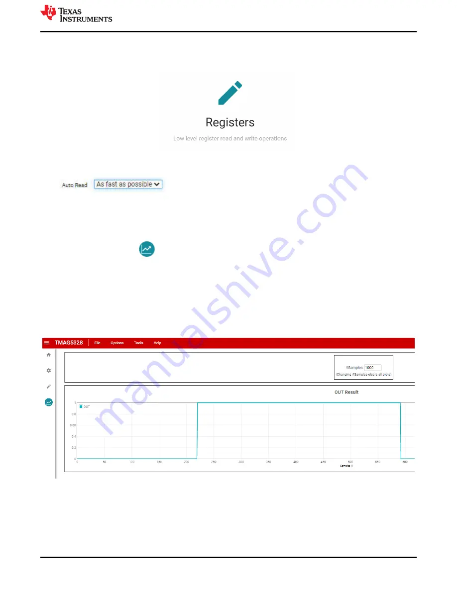
5.1.3.2.1 GUI Results Page
Click the
Results Data
icon
to view the
Results
page. This screen shows the state of the TMAG5328
OUT pin. Remember to set the "Auto Read" option on the
Registers
page to "As fast as possible" to view the
).
shows an example plot of the OUT waveform. If the TMAG5328 OUT pin is at a high state (LED is
OFF), a "1" is displayed on the graph. If the pin is at a low state (LED is ON), a "0" is displayed on the graph.
The number of samples stored in the plot can be modified by adjusting the "1000" at the top of the screen with
the desired number of samples then clicking enter. In addition, the plot can be exported by clicking the
SAVE
PLOT
button.
Figure 5-9. TMAG5328 GUI Results Page
5.1.3.2.2 GUI DAC Configuration Page
The DAC on the EVM is configured using the DAC configuration page on the GUI. When configuring the DAC
using the EVM, ensure that the EVM is configured to set the B
OP
using the DAC (see
). To go
EVM Operation
SBAU376 – DECEMBER 2021
TMAG5328 Evaluation Module
15
Copyright © 2021 Texas Instruments Incorporated