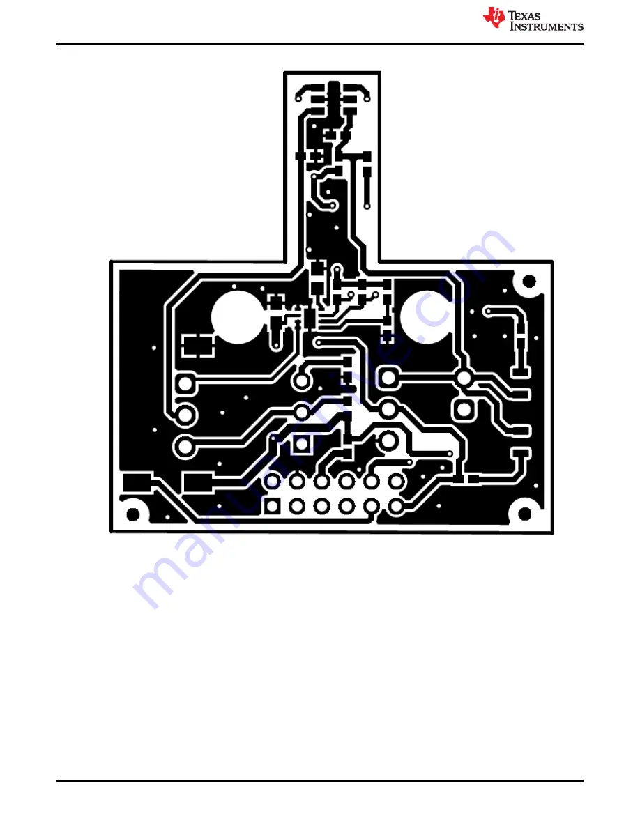
Figure 6-3. Top Layer
Schematics, PCB Layout, and Bill of Materials
www.ti.com
26
TMAG5328 Evaluation Module
SBAU376 – DECEMBER 2021
Submit Document Feedback
Copyright © 2021 Texas Instruments Incorporated
Page 1: ...cumentation From Texas Instruments 4 4 Hardware 5 4 1 EVM Threshold Adjustment Options 5 4 2 Power Supply Options and Jumper Settings 9 5 EVM Operation 12 5 1 Evaluation With SCB and GUI 12 5 2 Evalua...
Page 2: ...ADJ pin assuming that the voltage source can properly sink the current generated internally on the ADJ pin The TMAG5328EVM is an easy to use platform for evaluating the performance of the TMAG5328 Th...
Page 3: ...dynamically changing BOP by adjusting potentiometer position Resistor footprint for creating a static BOP External voltage supply LED on TMAG5328 output for visual inspection of switch s output state...
Page 4: ...t the time of the writing of this document Newer revisions are available from www ti com or the Texas Instruments Literature Response Center at 800 477 8924 or the Product Information Center at 972 64...
Page 5: ...ings are stored in the nonvolatile memory of the DAC a microcontroller does not need to reconfigure the DAC after each reset The DAC43701 can set the BOP of the TMAG5328 without using the SCB afterwar...
Page 6: ...ables one of these parameters at a time Desired BOP Desired voltage on the ADJ pin ADJ equivalent resistance This setting simulates applying a resistor on the ADJ pin by applying a voltage that would...
Page 7: ...ion of the EVM This circuit consists of a 10 k potentiometer R13 in series with a 4 3 k fixed resistor R2 When the potentiometer is used for setting the BOP the ADJ pin sees a resistance equal to the...
Page 8: ...Figure 4 4 and Figure 4 5 show the potentiometer positions that correspond to an ADJ resistance of 4 3k and 14 3 k respectively Figure 4 4 Potentiometer Position for Creating 4 3 k ADJ Resistance Hard...
Page 9: ...be sensed by the TMAG5328 Since the potentiometer isn t affected by power resets the potentiometer ensures that the same BOP is used after a power reset assuming that its position is not moved As a r...
Page 10: ...o the flexibility to the board Some of these headers require that jumpers be placed appropriately for the board to correctly function Table 4 1 shows the functionality of each header on the board Tabl...
Page 11: ...k See Section 4 1 3 for more details To set the BOP using an external voltage source remove the jumper on this pin so that no jumper is populated and also make sure that resistor R7 is not populated...
Page 12: ...ion of the firmware can be downloaded from It can also be downloaded onto the SCB from the GUI 5 1 2 1 Updating Firmware on SCB If the firmware gets corrupted or must be manually reinstalled for any r...
Page 13: ...run the bat file iii Unplug the USB cable from the PC after the firmware is flashed then plug the cable back in to reset the SCB b TMAG5328GUI i Go to the GUI menu bar and click File Program Device F...
Page 14: ...o download the TI Cloud Agent and browser extension shown in Figure 5 5 These prompts will appear after you close the README md dialog Figure 5 5 TI Cloud Agent 4 Click the icon in the GUI Composer wi...
Page 15: ...the Auto Read option on the Registers page to As fast as possible to view the results on this pin see Section 5 1 3 2 Figure 5 9 shows an example plot of the OUT waveform If the TMAG5328 OUT pin is a...
Page 16: ...eration was successful but the sensed magnetic flux density was less than the minimum 2 mT BOP supported by the device Magnetic Flux Density 2 mT device minimum Bop If the operation was not successful...
Page 17: ...equiring the microcontroller performing any reconfigurations steps on the DAC As a result the BOP also would be retained after the power cycle RELOAD FROM NVM button Sets the current DAC output voltag...
Page 18: ...lower case Figure 5 13 is an example response to this command Figure 5 13 Example Set BOP Command Response Set DAC Output Voltage command format wreg 1 VAL This command allows you to enter a desired...
Page 19: ...t into nonvolatile memory After power cycling the EVM the DAC output voltage will automatically be initiated to the value stored in nonvolatile memory thereby ensuring the same BOP value is used after...
Page 20: ...nd alone mode an external power supply must be connected to the TMAG5328EVM see Section 4 2 When in standby mode BOP can be set using either the DAC potentiometer or fixed resistor options Remember th...
Page 21: ...creates a magnetic field that is sensed by the TMAG5328 The module has two portions a screw and a base The base is connected to the EVM and the screw is placed inside the base A magnet is embedded wit...
Page 22: ...to TMAG5328EVM 2 Place the screw at the top of the base see Figure 5 23 As the screw is brought near the top of the base the sensed magnetic flux density will approach around 2 mT Figure 5 23 Screw P...
Page 23: ...e For more information on the Head On Linear Displacement attachment refer to the Head on Linear Displacement 3D Attachment user s guide 6 Schematics PCB Layout and Bill of Materials The following sec...
Page 24: ...s the EVM schematic Figure 6 1 TMAG5328EVM Schematic Schematics PCB Layout and Bill of Materials www ti com 24 TMAG5328 Evaluation Module SBAU376 DECEMBER 2021 Submit Document Feedback Copyright 2021...
Page 25: ...ure 6 5 show the PCB layers of the EVM Figure 6 2 Top View www ti com Schematics PCB Layout and Bill of Materials SBAU376 DECEMBER 2021 Submit Document Feedback TMAG5328 Evaluation Module 25 Copyright...
Page 26: ...Figure 6 3 Top Layer Schematics PCB Layout and Bill of Materials www ti com 26 TMAG5328 Evaluation Module SBAU376 DECEMBER 2021 Submit Document Feedback Copyright 2021 Texas Instruments Incorporated...
Page 27: ...Figure 6 4 Bottom View www ti com Schematics PCB Layout and Bill of Materials SBAU376 DECEMBER 2021 Submit Document Feedback TMAG5328 Evaluation Module 27 Copyright 2021 Texas Instruments Incorporated...
Page 28: ...igure 6 5 Bottom Layer Schematics PCB Layout and Bill of Materials www ti com 28 TMAG5328 Evaluation Module SBAU376 DECEMBER 2021 Submit Document Feedback Copyright 2021 Texas Instruments Incorporated...
Page 29: ...Cable USB A MALE to Micro B MALE 3 CDDS 6612041 6612041 Qualtek H3 1 Kitting Item D2X0 1 8 dia x 1 thick N42 magnet D2X0 K J Magnetics H4 1 Kitting Item D28 N52 1 8 dia x 1 2 thick N52 magnet D28 N52...
Page 30: ...Solutions TP1 TP2 TP3 3 Test Point SMT Test Point SMT S2751 46R Harwin U1 1 PTMAG5328QDBVR SOT23 6 PTMAG5328QDBVR Texas Instruments U2 1 8 bit single channel voltage output smart DAC with GPIO trigger...
Page 31: ...ther than TI b the nonconformity resulted from User s design specifications or instructions for such EVMs or improper system design or c User has not paid on time Testing and other quality control tec...
Page 32: ...These limits are designed to provide reasonable protection against harmful interference in a residential installation This equipment generates uses and can radiate radio frequency energy and if not in...
Page 33: ...instructions set forth by Radio Law of Japan which includes but is not limited to the instructions below with respect to EVMs which for the avoidance of doubt are stated strictly for convenience and s...
Page 34: ...any interfaces electronic and or mechanical between the EVM and any human body are designed with suitable isolation and means to safely limit accessible leakage currents to minimize the risk of electr...
Page 35: ...R DAMAGES ARE CLAIMED THE EXISTENCE OF MORE THAN ONE CLAIM SHALL NOT ENLARGE OR EXTEND THIS LIMIT 9 Return Policy Except as otherwise provided TI does not offer any refunds returns or exchanges Furthe...
Page 36: ...change without notice TI grants you permission to use these resources only for development of an application that uses the TI products described in the resource Other reproduction and display of thes...