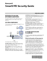
EVM Board Layout
2-3
Physical Description
Figure 2–1. EVM Board Layout
–+
–+
–
+
J5
Speaker
J1
Phone Plug
J7
Analog In
J6
Speaker
J12
Microphone
J8
Analog In
J9
W40
W59
W55
W56
W52
W53
TP13
J15
J10
C54 Perpheral
W50
W49
W47
W43
W44
W58
W57
W54
W51
W48
W46
W45
W42
TL
V320AIC10/1
1 – EVM
P/N: EVM–0301 REV
A
S/N
TP3
TP2
W7
1 2 3
1 2 3
W19
–
+
J4
J3
–
+
TP4
TP5
U12
U10
U13
TP6
TP7
1 2 3
1 2 3
W2
W3
Q1
U9
––
+–
B1
W8
U1
1
TP10
TP1
1
TP12
U1
1 2 3
U2
U3
U4
U5
U6
U7
U8
W61
1 2 3
W1
1
1 2 3
1 2 3
1 2 3
W1
W4
W5
W35
W36
D3
TP9
TP8
U18
1 2 3
1 2 3
W12
W22
D2
RED
GREEN
U14
U15
SW1
U19
1 2 3
1 2 3
W20
W16
T
exas Instruments – 2000
1 2 3
W18
1 2 3
W17
1 2 3
W15
1 2 3
W13
SW2
ON
OFF
1
12
W21
1 2 3
W14
U16
1 2 3
W6
J2
–
+
W38
W37
W60
W39
W41
1 2 3
1 2 3
W9
W10
Summary of Contents for TLV320AIC10 EVM
Page 1: ... January 2001 AAP Data Converters User s Guide SLWU003D ...
Page 4: ...iv ...
Page 12: ...1 6 ...
Page 34: ...5 6 ...
Page 38: ...Printed Circuit Board Rev C 6 4 Figure 6 3 Printed Circuit Board Layer 1 Rev C ...
Page 40: ...Printed Circuit Board Rev C 6 6 Figure 6 5 Printed Circuit Board Layer 3 Rev C ...
Page 42: ...Printed Circuit Board Rev C 6 8 Figure 6 7 Printed Circuit Board Layer 5 Rev C ...