Input and Output Connections
3
SBOU229 – August 2019
Copyright © 2019, Texas Instruments Incorporated
THS6222RHF Evaluation Module
3
Input and Output Connections
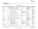
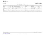
The THS6222RHFEVM is equipped with SMA connectors for easy connection of signal generators and
analysis equipment. As shipped, the EVM is configured for a gain of 10-V/V, split-supply, differential input
and output with 50-
Ω
termination. By default, the inputs INA and INB are configured for a differential input
connection. To use the device with a single-ended input, either use an external transformer or populate
transformer T1 on the board, remove R21, populate R15 with a 0-
Ω
resistor, and use INA as the single-
ended input. OUTA (J5) is the output connector for single-ended output signals. The output resistors R10
and R11 in combination with the transformer (T2) on the amplifier output provide a 25-
Ω
load to the
amplifier when terminated in 50
Ω
differentially. To use the EVM with a single-ended output, remove
resistor R23 and populate resistor R18 with 0
Ω
, which gives a single-ended output on OUTA. The EVM
contains provisions for additional output devices to change the loading of the amplifier and to add
protection devices. See the
applications section, schematics, and layouts for more
detail and how to reconfigure the EVM.
3.1
Bias Mode Control Pins
The amplifier bias modes can be controlled through shorting jumpers J1 and J2. By default, the jumper
shorts are left unconnected, which pulls the input signals low, leaving the device in its full-bias mode.
Jumper J1 controls pin BIAS-1 and jumper J2 controls pin BIAS-2. In conjunction the jumpers can be used
to place the device in its three bias modes or in shutdown.
3.2
IREF Pin Connection
The fine current adjustment (IADJ) pin of the device is controlled using the potentiometer R17 on the
board. By default the potentiometer is set to 0
Ω
, which yields the maximum quiescent current for each
bias mode. By increasing the resistance of the potentiometer, the quiescent current can be reduced to a
desired lowered value at the cost of reduced performance.
3.3
Optional VCM Pin Connection
The EVM includes an optional connection on the VCM (pin 5) of the device for a capacitor. The optional
VCM capacitor can be added to help filter common-mode noise if needed by the application. VCM is not
populated by default on the EVM.

