background image

Schematic and Bill of Materials

www.ti.com

6

SBOU229 – August 2019

Submit Documentation Feedback

Copyright © 2019, Texas Instruments Incorporated

THS6222RHF Evaluation Module

5.2

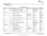
Bill of Materials

Table 2

lists the EVM BOM.

Table 2. Bill of Materials

Designator

Qty

Value

Description

Package Reference

Part Number

Manufacturer

C1, C2

2

2.2uF

CAP, CERM, 2.2 uF, 50 V, +/- 10%, X7R, 0805

805

C2012X7R1H225K125AC

TDK

C3

1

1000pF CAP, CERM, 1000 pF, 100 V, +/- 20%, X7R, 0603

603

CX0603MRX7R0BB102

Yageo America

C4

1

0.01uF

CAP, CERM, 0.01 uF, 50 V, +/- 10%, X7R, 0805

805

08055C103KAT2A

AVX

C9, C10

2

0.1uF

CAP, CERM, 0.1 uF, 25 V, +/- 5%, X7R, 0603

603

C0603C104J3RACTU

Kemet

H1, H2, H3, H4

4

Machine Screw, Round, #4-40 x 1/4, Nylon, Philips panhead

Screw

NY PMS 440 0025 PH

B&F Fastener
Supply

H5, H6, H7, H8

4

Standoff, Hex, 0.5"L #4-40 Nylon

Standoff

1902C

Keystone

J1, J2

2

Header, 100mil, 2x1, Gold, TH

Sullins 100mil, 1x2, 230
mil above insulator

PBC02SAAN

Sullins Connector
Solutions

J3, J4, J5, J6

4

Connector, End launch SMA, 50 ohm, SMT

SMA End Launch

142-0701-851

Cinch Connectivity

J7

1

Terminal Block, 5.08 mm, 3x1, Brass, TH

3x1 5.08 mm Terminal
Block

ED120/3DS

On-Shore
Technology

L1, L2

2

90 ohm Ferrite Bead, 90 ohm @ 100 MHz, 1.5 A, 1206

1206

MI1206K900R-10

Laird-Signal
Integrity Products

LBL1

1

Thermal Transfer Printable Labels, 0.650" W x 0.200" H - 10,000
per roll

PCB Label 0.650 x 0.200
inch

THT-14-423-10

Brady

R1, R2

2

24.9

RES, 24.9, 1%, 0.1 W, AEC-Q200 Grade 0, 0402

402

ERJ-2RKF24R9X

Panasonic

R3, R4, R5, R6

4

10k

RES, 10 k, 5%, 0.1 W, 0603

603

RC1608J103CS

Samsung Electro-
Mechanics

R7, R8

2

1.24k

RES, 1.24 k, 1%, 0.063 W, AEC-Q200 Grade 0, 0402

402

CRCW04021K24FKED

Vishay-Dale

R9

1

274

RES, 274, 1%, 0.063 W, AEC-Q200 Grade 0, 0402

402

CRCW0402274RFKED

Vishay-Dale

R10, R11

2

24.9

RES, 24.9, 1%, 0.1 W, 0603

603

RC0603FR-0724R9L

Yageo

R14, R23, R26, R27

4

0

RES, 0, 5%, 0.1 W, 0603

603

RC0603JR-070RL

Yageo

R16, R21, R22

3

0

RES, 0, 5%, 0.063 W, 0402

402

RC0402JR-070RL

Yageo America

R17

1

10k
ohm

TRIMMER 10k OHM 0.125W SMD

3.52x4.16x3.94mm

3223W-1-103E

Bourns

T2

1

RF Transformer, 50ohm, 0.004 to 300 MHz, SMT

7.62x6.86mm

TT1-6-KK81+

Minicircuits

TP1

1

Test Point, Miniature, Red, TH

Red Miniature Testpoint

5000

Keystone

TP4, TP5

2

Test Point, Miniature, Black, TH

Black Miniature Testpoint

5001

Keystone

U1

1

THS6222IRHF, RHF0024A (VQFN-24)

RHF0024A

THS6222IRHF

Texas Instruments

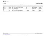
C5, C6, C7, C8, C11,
C12, C13, C14

0

0.1uF

CAP, CERM, 0.1 uF, 25 V, +/- 5%, X7R, 0603

603

C0603C104J3RACTU

Kemet

D1

0

27V

Diode, TVS, Uni, 27 V, 38 Vc, SOT-23

SOT-23

MMBZ27VCL-7-F

Diodes Inc.

Summary of Contents for THS6222RHFEVM

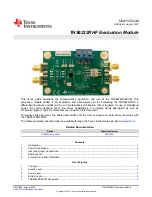
Page 1: ...ine communications PLC line driver applications A complete circuit description as well as schematic diagram and bill of materials are included in this document Throughout this document the abbreviation EVM and the term evaluation module are synonymous with the THS6222RHFEVM The following related documentation is available through the Texas Instruments web site at www ti com Related Documentation D...

Page 2: ...gle ended output 1 1 Features Configured for split supply operation and easily modified for single supply Default gain of 10 V V configuration can easily be reconfigured for other gains Designed for easy connection to standard 50 Ω input output impedance test equipment Inputs and outputs include subminiature version A SMA connectors 1 2 EVM Specifications Table 1 lists the typical performance spec...

Page 3: ...OUTA The EVM contains provisions for additional output devices to change the loading of the amplifier and to add protection devices See the THS6222 data sheet applications section schematics and layouts for more detail and how to reconfigure the EVM 3 1 Bias Mode Control Pins The amplifier bias modes can be controlled through shorting jumpers J1 and J2 By default the jumper shorts are left unconne...

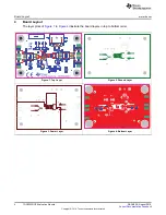
Page 4: ...edback Copyright 2019 Texas Instruments Incorporated THS6222RHF Evaluation Module 4 Board Layout The layer plots of Figure 1 to Figure 4 illustrate the board layers in top to bottom order Figure 1 Top Layer Figure 2 Ground Layer Figure 3 Power Layer Figure 4 Bottom Layer ...

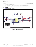
Page 5: ...24 9 R2 0 R16 1 24k R8 1 24k R7 274 R9 10k R3 10k R4 10k R5 10k R6 24 9 R10 24 9 R11 49 9 R12 49 9 R13 1 2 3 4 5 6 T2 TT1 6 KK81 0 R14 GND 0 R18 1 2 3 4 5 J5 OUT A 1 2 3 4 5 J6 OUT B GND 0 R19 GND 0 R20 100nF 25V C5 100nF 25V C6 GND GND 100nF 25V C7 100nF 25V C8 GND 100nF 25V C9 100nF 25V C10 GND GND 0 R22 0 R21 GND GND 0 R23 100nF 25V C12 100nF 25V C11 TP2 OUT A TP3 OUT B TP4 GND GND TP5 GND GND ...

Page 6: ... L2 2 90 ohm Ferrite Bead 90 ohm 100 MHz 1 5 A 1206 1206 MI1206K900R 10 Laird Signal Integrity Products LBL1 1 Thermal Transfer Printable Labels 0 650 W x 0 200 H 10 000 per roll PCB Label 0 650 x 0 200 inch THT 14 423 10 Brady R1 R2 2 24 9 RES 24 9 1 0 1 W AEC Q200 Grade 0 0402 402 ERJ 2RKF24R9X Panasonic R3 R4 R5 R6 4 10k RES 10 k 5 0 1 W 0603 603 RC1608J103CS Samsung Electro Mechanics R7 R8 2 1...

Page 7: ... Manufacturer D2 D3 0 30V Diode Schottky 30 V 0 2 A SOT 23 SOT 23 BAT54S 7 F Diodes Inc R12 R13 0 49 9 RES 49 9 1 0 063 W AEC Q200 Grade 0 0402 402 CRCW040249R9FKED Vishay Dale R15 R19 0 0 RES 0 5 0 063 W 0402 402 RC0402JR 070RL Yageo America R18 R20 R24 R25 R28 0 0 RES 0 5 0 1 W 0603 603 RC0603JR 070RL Yageo T1 0 RF Transformer 50ohm 0 004 to 300 MHz SMT 7 62x6 86mm TT1 6 KK81 Minicircuits TP2 TP...

Page 8: ...other than TI b the nonconformity resulted from User s design specifications or instructions for such EVMs or improper system design or c User has not paid on time Testing and other quality control techniques are used to the extent TI deems necessary TI does not test all parameters of each EVM User s claims against TI under this Section 2 are void if User fails to notify TI of any apparent defects...

Page 9: ... These limits are designed to provide reasonable protection against harmful interference in a residential installation This equipment generates uses and can radiate radio frequency energy and if not installed and used in accordance with the instructions may cause harmful interference to radio communications However there is no guarantee that interference will not occur in a particular installation...

Page 10: ...y for convenience and should be verified by User 1 Use EVMs in a shielded room or any other test facility as defined in the notification 173 issued by Ministry of Internal Affairs and Communications on March 28 2006 based on Sub section 1 1 of Article 6 of the Ministry s Rule for Enforcement of Radio Law of Japan 2 Use EVMs only after User obtains the license of Test Radio Station as provided in R...

Page 11: ... any interfaces electronic and or mechanical between the EVM and any human body are designed with suitable isolation and means to safely limit accessible leakage currents to minimize the risk of electrical shock hazard User assumes all responsibility and liability for any improper or unsafe handling or use of the EVM by User or its employees affiliates contractors or designees 4 4 User assumes all...

Page 12: ...OR DAMAGES ARE CLAIMED THE EXISTENCE OF MORE THAN ONE CLAIM SHALL NOT ENLARGE OR EXTEND THIS LIMIT 9 Return Policy Except as otherwise provided TI does not offer any refunds returns or exchanges Furthermore no return of EVM s will be accepted if the package has been opened and no return of the EVM s will be accepted if they are damaged or otherwise not in a resalable condition If User feels it has...

Page 13: ...se resources are subject to change without notice TI grants you permission to use these resources only for development of an application that uses the TI products described in the resource Other reproduction and display of these resources is prohibited No license is granted to any other TI intellectual property right or to any third party intellectual property right TI disclaims responsibility for...

Reviews: