


Public Version
PRCM Functional Description
www.ti.com
3.5.3.6.4 DPLL Clock Path Power Down
DPLL3 and DPLL4 can power down the CLKOUTX2 path. A small section of logic is powered down,
because the M2 post divider is shared with the CLKOUT path, which remains functional.
The HSDIVIDER can power down each CLKOUTn path (with n in the range of 3 to 6) independently,
therefore allowing further power savings. The clock output path is also powered down when the DPLL is in
stop mode, regardless of the software setting.
Software must ensure correct sequencing of the control. To avoid a glitch at the output, activate this
control when the clock is not required, and when the output clock is gated. Conversely, ensure a delay
between deactivation and reactivation of the clock by using the power-down control.
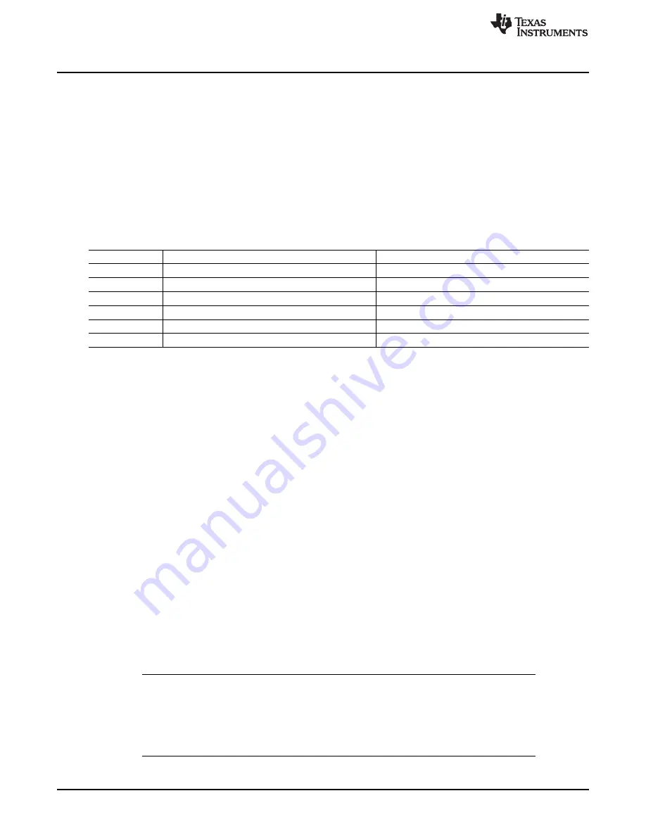
lists the bit fields and the corresponding clock outputs of the DPLLs.
Table 3-43. Clock Path Power-Down Control
DPLL
Control Bit Field
Clock Path
DPLL4
PRCM.
[27] PWRDN_96M
96-MHz clock output (DPLL4 output M2)
PRCM.
[28] PWRDN_TV
DSS TV clock output (DPLL4 output M3)
PRCM.
[29] PWRDN_DSS1
DSS1 clock output (DPLL4 output M4)
PRCM.
[30] PWRDN_CAM
CAM clock output (DPLL4 output M5)
PRCM.
[31] PWRDN_EMU_PERIPH
EMU_PERIPH clock output (DPLL4 output M6)
DPLL3
PRCM.
[12] PWRDN_EMU_CORE
EMU_CORE clock output (DPLL3 output M3X2)
3.5.3.6.5 Recalibration
A lock sequence occurs during an initial lock or during a relock following a new multiplier or divider value.
Each time the DPLL is reset or performs a lock sequence, it performs a recalibration of the output
frequency, based on voltage and temperature conditions. By compensating for voltage and temperature
changes within a certain range, calibration allows the lock frequency to remain steady. If the voltage or
temperature drifts outside the acceptable range, the DPLL asserts a recalibration flag.
For example, a large temperature drift can cause the DPLL to lose its lock and require recalibration. When
the DPLL locks at a temperature within the 080 degrees Celsius range, the maximum temperature drift is
approximately 55 degrees Celsius. When DPLL starts at a negative temperature, the maximum
temperature drift is higher.
If the DPLL locks at 30 degrees Celsius, the temperature can change by 60 degrees Celsius (from 30 to
+90 degrees Celsius) and the DPLL does not lose the lock. However, for temperatures above the 60
degrees Celsius range, the DPLL may need to be relocked. A new relock sequence reinitializes the
starting temperature.
This compensation mechanism is active only while the DPLL is locked. When the DPLL is in off or bypass
mode (low-power or fast-relock), it does not assert the recalibration flag. If the voltage or temperature
exceeds the drift limits while the DPLL is not locked, and then the DPLL tries to relock, the DPLL fails to
lock within the normal delay and recalibrates automatically before eventually locking. The only difference
from a standard relock is the delay.
The DPLL can automatically start recalibration when the recalibration flag is asserted, or recalibration can
be managed by the software. The mode of operation is selected by configuring the corresponding
registers in the PRCM module (see
). The software or manual control mode is selected by
default.
NOTE:
Automatic recalibration of the DPLL can start at any time. While relocking, the DPLL
switches to bypass mode. For modules that are sensitive to frequency change while
operating, this can introduce operational instability. For example, the SDRC is sensitive to a
frequency change on DPLL3 because its embedded DLL relocks on a frequency change.
Any access during this DLL relock period can be corrupted. It is important; therefore, to stall
SDRC access during DPLL recalibration.
332
Power, Reset, and Clock Management
SWPU177N – December 2009 – Revised November 2010
Copyright © 2009–2010, Texas Instruments Incorporated