AES_ACCEL Registers
449
SLAU208Q – June 2008 – Revised March 2018
Copyright © 2008–2018, Texas Instruments Incorporated
AES Accelerator
15.3.1 AESACTL0 Register
AES Accelerator Control Register 0
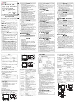
AESACTL0 is shown in
and described in
.
Figure 15-6. AESACTL0 Register
15
14
13
12
11
10
9
8
Reserved
AESRDYIE
AESERRFG
Reserved
AESRDYIFG
r0
r0
r0
rw-0
rw-0
r0
r0
rw-0
7
6
5
4
3
2
1
0
AESSWRST
Reserved
AESOPx
rw-0
r0
r0
r0
rw-0
rw-0
rw-0
rw-0
Table 15-2. AESACTL0 Register Description
Bit
Field
Type
Reset
Description
15-13
Reserved
R
0h
Reserved
12
AESRDYIE
RW
0h
AES ready interrupt enable. AESRDYIE is not reset by AESSWRST = 1.
0 = Interrupt disabled
1 = Interrupt enabled
11
AESERRFG
RW
0h
AES error flag. AESAKEY or AESADIN were written while an AES operation was
in progress. The bit must be cleared by software.
0 = No error
1 = Error occurred
10-9
Reserved
R
0h
Reserved
8
AESRDYIFG
RW
0h
AES ready interrupt flag. Set when the selected AES operation was completed
and the result can be read from AESADOUT. Automatically cleared when
AESADOUT is read or AESAKEY or AESADIN is written.
0 = No interrupt pending
1 = Interrupt pending
7
AESSWRST
RW
0h
AES software reset. Immediately resets the complete AES accelerator module
even when busy except for the AESRDYIE and AESOPx bits.
The AESSWRST bit is automatically reset and always reads as zero.
0 = No reset
1 = Reset AES accelerator module
6-2
Reserved
R
0h
Reserved
1-0
AESOPx
RW
0h
AES operation. The AESOPx bits are not reset by AESSWRST = 1.
00 = Encryption
01 = Decryption. The provided key is the same key used for encryption.
10 = Generate first round key required for decryption.
11 = Decryption. The provided key is the first round key required for decryption.