DRV821xDSG
VM
1
OUT1
2
OUT2
3
GND
4
VCC
8
MODE
7
IN1
6
IN2
5
Thermal
Pad
BDC
V
M
0.1
…
F
C
Bulk
V
M
0.1
…
F
Controller
PWM
V
CC
O
X
R
Limit
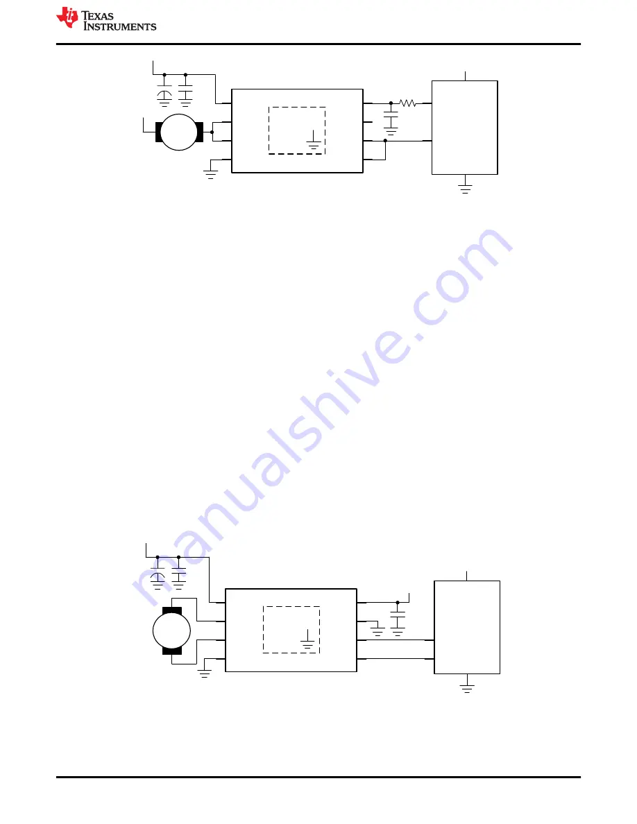
Figure 6-4. Half-bridge mode used as a low-side driver with outputs paralleled
6.2 Single Motor Operation
This mode allows for bidirectional control of one motor. Connect a DC motor across OUT1 and OUT2. Reversing
direction is controlled by the potentiometer. This is described in detail in
. Use the following steps to
operate the EVM with a signal motor and bidirectional speed control:
1. Make sure only one driver is populated and no power is being supplied to the EVM.
2. Connect a motor across OUT1 and OUT2. See
for a block diagram of the DRV821xDSG.
3. If the DRV821xDSG is populated on the EVM, use a jumper to connect the MODE/nSLEEP header (J2) to
3.3 V or GND to set the input mode to PWM control mode or PH/EN mode respectively.
4. If the DRV8220DSG is populated on the EVM, use a jumper to connect the MODE/nSLEEP header (J2) to
3.3 V or GND to set the input mode to PWM control mode or PH/EN mode respectively. Also connect
VCC_DRV (J7) to 3.3V via a jumper to enable the device.
5. If the DRV821xPDSG is populated, connect the MODE/nSLEEP header to 3.3V to set nSLEEP logic high and
enable the device (The MODE pin becomes the nSLEEP pin for the PDSG devices). The DRV821xPDSG
only supports PWM control mode.
6. If a DRV82xxDRL is populated, the state of the MODE/nSLEEP jumper is ignored and the control mode is set
to PWM by default. The DRL devices only support PWM control mode.
7. Adjust the potentiometer, EN/IN1 PWM and PH/IN2 PWM, to minimum voltage by turning the wheel counter-
clockwise all the way. This minimizes the speed of the motor connected across OUT1 and OUT2.
8. Apply power to J1 header.
9. Turn potentiometer, EN/IN1 PWM, clockwise and the motor connected across OUT1 and OUT2 will begin to
turn. Continue adjusting, as desired, until the maximum speed is reached.
10.Control the motor direction and speed by adjusting the potentiometers according to the tables in
Controller
PWM
PWM
V
CC
DRV821xDSG
VM
1
OUT1
2
OUT2
3
GND
4
VCC
8
MODE
7
IN1
6
IN2
5
Thermal
Pad
BDC
0.1
…
F
C
Bulk
V
M
V
CC
0.1
…
F
Figure 6-5. DRV821xDSG PWM single motor operation
Operation of the EVM
SLOU540A – NOVEMBER 2020 – REVISED DECEMBER 2020
DRV821xEVM and DRV8220EVM User's Guide
13
Copyright © 2020 Texas Instruments Incorporated


