


www.ti.com
Hardware Configuration
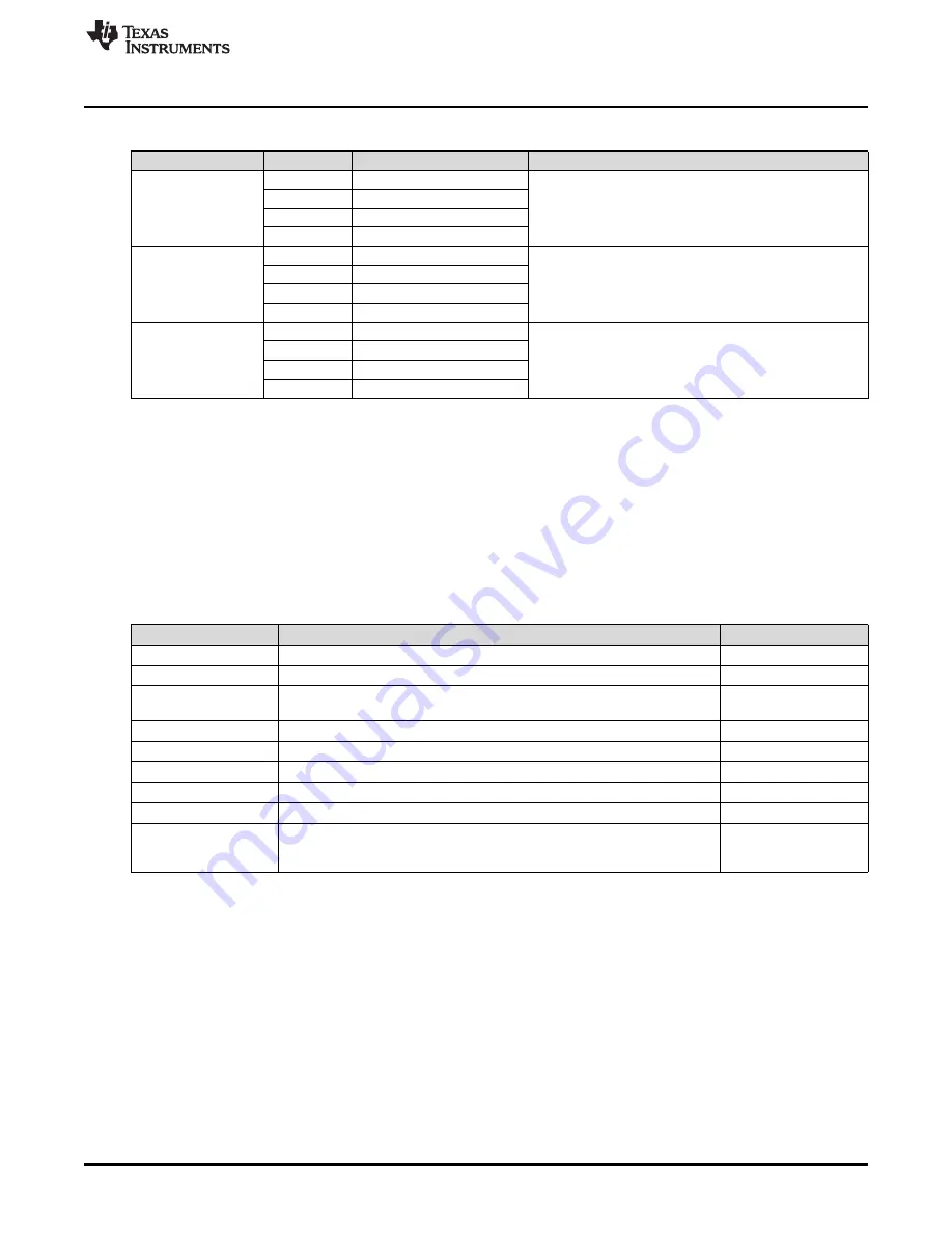
Table 4. Binary Counting Modes (continued)
Mode
Button
Description
Notes
B1
5 ms playback interval enabled
Playback interval - demonstrates the 1 ms or 5 ms playback
Mode 13
B2
1 ms playback interval enabled
interval. Affects buzz waveform by multiplying the time data either
ROM Playback Interval
by 1 ms or 5 ms. B1 - 5 ms mode enabled, B2 - 1 ms mode
B3
Selects ERM or LRA
LEDs: 01101
enabled, B3 - selects between ERM or LRA.
B4
B1
Begin actuator break-in
Mode 30
B2
Actuator break-in
Actuator break-in - used to break in new actuators
B3
LEDs: 11110
B4
B1
Device ID
Mode 31
B2
Silicon revision
About the board - the value appears on the mode LEDs in binary.
About the board
DRV2605L Device ID = 00011
B3
Code revision
LEDs: 11111
B4
4
Hardware Configuration
The DRV2605LEVM-CT is flexible and can be used to completely evaluate the DRV2605L. The following
sections list the various hardware configurations.
4.1
Input and Output Overview
The DRV2605LEVM-CT allows complete evaluation of the DRV2605L though test points, jacks, and
connectors.
Table 5
gives a brief description of the hardware.
Table 5. Hardware Overview
Signal
Description
I/O
PWM
External input to DRV2605L IN/TRIG pin
Input / Observe
EN
External DRV2605L enable control
Input / Observe
Filtered output test points for observation, connect to oscilloscope, or
OUT+ / OUT–
Output
measurement equipment
OUT
Unfiltered output terminal block, connect to actuator
Output
USB
USB power (5 V)
Input
VBAT
External supply power (2.5 to 5.5 V)
Input
SBW
MSP430 programming header
Input / Output
I
2
C
DRV2605L and MSP430 I
2
C bus
Input / Output
The audio jack is connected to the IN/TRIG pin of the DRV2605L. When the
Audio
DRV2605L is in audio-to-haptics mode, audio from this jack is converted to
Input
haptics
Hardware configuration details can be found in the following sections.
4.2
Power Supply Selection
The DRV2605LEVM-CT can be powered by USB or an external power supply (VBAT). Jumpers “DRV”
and “MSP” are used to select USB or VBAT for the DRV2605L and MSP430G2553, respectively. See the
following table for possible configurations.
17
SLOU389A – May 2014 – Revised June 2014
DRV2605L ERM and LRA Haptic Driver Evaluation Kit
Submit Documentation Feedback
Copyright © 2014, Texas Instruments Incorporated