


Additional Hardware Modes
www.ti.com
3.3
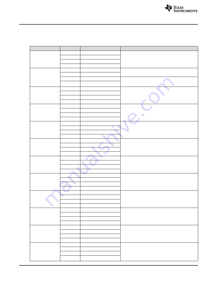
Binary Counting Modes
Table 4
lists the modes available in “binary counting mode”.
Table 4. Binary Counting Modes
Mode
Button
Description
Notes
B1
Set ERM output
Use this mode to control the DRV2605L using an external I
2
C
Mode 0
B2
Set LRA output
Master. Press B1 or B2 to choose between the ERM or LRA. Press
External I
2
C mode
B3 to choose the trigger type. (1 - Internal, 2 - External edge, 3 -
B3
Choose trigger
LEDs: 00000
External level). Press B4 to trigger the waveform sequencer.
B4
Trigger button
B1
ERM auto-calibration
Run the auto-calibration. The new auto-calibration results are used
Mode 1
for all board effects, 1 flash = successful, 3 flashes = error.
B2
LRA auto-calibration
Auto-calibration and
diagnostics
B3
ERM diagnostics
Run diagnostics, 1 flash = successful, 3 flashes = error. The status
LEDs: 00001
register bits [3:0] are displayed on the mode LEDs [3:0] when
B4
LRA diagnostics
complete.
B1
Disable PWM mode
Mode 2
External PWM - disconnect MSP430 PWM using JP1. Connect
B2
Set ERM output
External PWM
external PWM signal to the "PWM" test point at the top of the
B3
Set LRA output
LEDs: 00010
board. Select actuator using buttons B2 and B3.
B4
–
B1
Return to typical mode
External PWM and enable - disconnect MSP430 PWM using JP1.
Mode 3
Connect external PWM signal to the "PWM" test point at the top of
B2
Set ERM output
External PWM and
the board. Connect an external enable signal to the "EN" test point.
enable
B3
Set LRA output
Select actuator using buttons B2 and B3. Press B1 before switching
LEDs: 00011
modes.
B4
–
B1
AC coupling - ERM
Mode 4
B2
DC coupling - ERM
Analog input - apply an external analog signal for AC coupling on
Analog Input
the "audio" jack. Apply a DC coupled signal to the "PWM" test point.
B3
AC coupling - LRA
LEDs: 00100
B4
DC coupling - LRA
B1
Alert (auto-resonance on)
Mode 5
Vary the auto-resonance off (open-loop) output frequency and see
B2
Alert (auto-resonance off)
Auto-resonance OFF
the change in vibration force over frequency. Hold B3 or B4 for
frequency adjust
quick frequency adjustment. Compare B2 (auto-resonance off) with
B3
Decrease output frequency
LEDs:00101
B1 (auto-resonance on).
B4
Increase output frequency
B1
Begin life test
Life test using RTP (2 seconds on, 1 second off) - life test repeats
Mode 6
infinite times and board must be powered down to stop. Increment
B2
Test buzz
Life test (RTP)
or decrement amplitude using B3 and B4. Test new amplitude using
2s ON, 1s OFF
B3
Decrease output voltage (–1)
B2. Choose actuator using buttons B1 and B2 in mode 0 or mode
LEDs: 00110
1.
B4
Increase output voltage (+1)
B1
Begin life test
Mode 7
Life test using RTP (infinite buzz) - board must be powered down to
B2
Test buzz
Life test (RTP)
stop buzz. Increment or decrement amplitude using B3 and B4.
Infinite buzz
Test new amplitude using B2 before beginning life test. Choose
B3
Decrease output voltage (–1)
LEDs: 00111
actuator using buttons B1 and B2 in mode 0 and mode 1.
B4
Increase output voltage (+1)
B1
Begin life test
Life test using PWM (2 seconds on, 1 second off) - life test repeats
Mode 8
infinite times and board must be powered down to stop. Increment
B2
Test buzz
Life test (PWM)
or decrement amplitude using B3 and B4. Test new amplitude using
2s ON, 1s OFF
B3
Decrease output voltage (–1)
B2. Choose actuator using buttons B1 and B2 in mode 0 or mode
LEDs: 01000
1.
B4
Increase output voltage (+1)
B1
Start or stop recording
Recorder - use this mode to create a single amplitude pattern. Start
Mode 9
B2
Create effect
by pressing the record button (B1), then use B2 to create the
Recorder
pattern by tapping the button. When finished, press the play back
B3
Start or stop play back
LEDs: 01001
button (B3).
B4
–
B1
BuzzAlert @ Frequency
Frequency Sweep (ROM Mode) - Increment or decrement the
Mode 11
B2
BuzzAlert @ Resonance
frequency using B3 and B4. B1 - Start/stop buzz alert at chosen
Frequency Sweep
frequency. B2 - Start/Stop buzz alert using auto-resonance.
B3
Decrease Frequency (–1)
LEDs: 01011
Frequency range: (50 Hz – 300 Hz)
B4
Increase Frequency (+1)
B1
Never transition to open loop
2nd Cycle Test - for this mode, connect a resistor of 20
Ω
(min of 8
Ω
, max of 25
Ω
) to simulate the resistance of a frozen actuator. B1
Mode 12
B2
Auto-transition to OL drive
plays a buzz alert with OL drive disabled. B2 plays a buzz alert with
2nd Cycle Test
the automatic transition to open loop drive enabled (when back-
B3
LEDs: 01100
EMF not detected). Demonstrates DRV2605L improved algorithm to
B4
sync.
16
DRV2605L ERM and LRA Haptic Driver Evaluation Kit
SLOU389A – May 2014 – Revised June 2014
Submit Documentation Feedback
Copyright © 2014, Texas Instruments Incorporated