Texas Instruments ADS9224REVM-PDK User Manual Download Page 7

www.ti.com

Analog Interface

7

SBAU315A – July 2018 – Revised June 2019

Submit Documentation Feedback

Copyright © 2018–2019, Texas Instruments Incorporated

ADS9224REVM-PDK

2.3

ADS9224R Internal Reference

The ADS9224R device incorporates an internal 2.5-V band-gap reference and independently matched
reference buffers for each ADC. The internal reference output pin (REFOUT) is decoupled with a 1-µF
capacitor and can be probed at test point TP8. The internally matched reference buffers provide a gain of
1.6384 V/V. These reference buffers generate a high-precision, 4.096-V reference voltage for each ADC
channel at pins REFP_A and REFP_B. These pins are decoupled with 10-µF decoupling capacitors.
Additionally, a mid-reference output (REFby2) is available at test point TP5. This internal REFby2 buffer
provides a common-mode voltage for input amplifiers driving the ADC inputs.

3

Digital Interfaces

As noted in

Section 1

the EVM interfaces with the PHI that, in turn, communicates with the computer

using the USB interface. There are two devices on the EVM that communicate with the PHI: the
ADS9224R ADC (over SPI or multiSPI) and the EEPROM (over I

2

C). The EEPROM comes

preprogrammed with the information required to configure and initialize the ADS9224REVM-PDK platform.
After the hardware is initialized, the EEPROM is no longer used.

3.1

multiSPI™ for ADC Digital IO

The ADS9224REVM-PDK supports several interface modes, as detailed in the

ADS9224R data sheet

. In

addition to the standard SPI modes (single-, dual-, and quad-SDO lines), the multiSPI modes support
single- and dual-data output rates. The PHI is capable of operating at a 3.3-V logic level and is directly
connected to the digital I/O lines of the ADC.

Table 3

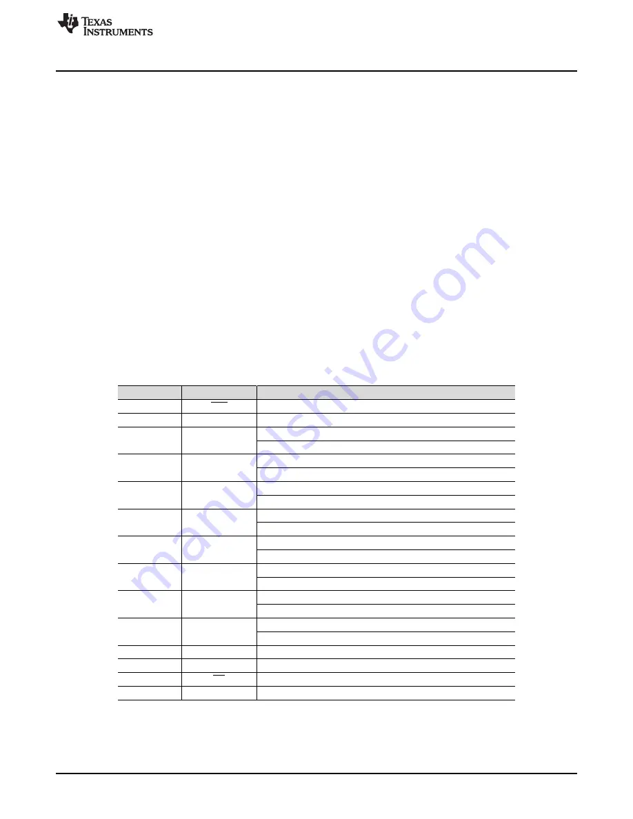
lists the test points available for probing the SPI pins

in both SPI and parallel byte mode.

Table 3. SPI Test Points

Designator

Signal

Description

TP1

RST

Asynchronous reset; active low.

TP2

READY/STR

Indicates data-ready or strobe output for data capture.

TP3

SDO-0/0A

SPI mode: data output 0 for channel A.

Parallel byte mode: least significant bit (LSB) from the data byte.

TP4

SDO-1/1A

SPI mode: data output 1 for channel A.

Parallel byte mode: LSB+1 from the data byte.

TP6

SDO-2/2A

SPI mode: data output 2 for channel A.

Parallel byte mode: LSB+2 from the data byte.

TP7

SDO-3/3A

SPI mode: data output 3 for channel A.

Parallel byte mode: LSB+3 from the data byte.

TP9

SDO-4/0B

SPI mode: data output 4 for channel A.

Parallel byte mode: LSB+4 from the data byte.

TP10

SDO-5/1B

SPI mode: data output 5 for channel A.

Parallel byte mode: LSB+5 from the data byte.

TP11

SDO-6/2B

SPI mode: data output 6 for channel A.

Parallel byte mode: LSB+6 from the data byte.

TP12

SDO-7/3B

SPI mode: data output 7 for channel A.

Parallel byte mode: MSB from the data byte.

TP13

SCLK

Clock input pin for the serial interface.

TP14

SDI

Serial data input pin.

TP15

CS

Chip-select input pin; active low.

TP16

CONVST

Conversion start input pin.

Summary of Contents for ADS9224REVM-PDK

Page 1: ...e evaluation of the ADS9224R device with hardware software and computer connectivity through a universal serial bus USB interface Throughout this document the terms evaluation board evaluation module...

Page 2: ...Materials 19 7 2 PCB Layout 23 7 3 Schematics 26 List of Figures 1 THS4551 Differential Input Driving Path 6 2 THS4551 Fully Differential Amplifier Driver 6 3 ADS9224REVM PDK Jumper Locations 9 4 ADS...

Page 3: ...ply Test Points 8 5 Default Jumper Configurations 9 6 External Source Requirements for Evaluation of the ADS9224R 17 7 ADS9224REVM Bill of Materials 19 Trademarks multiSPI is a trademark of Texas Inst...

Page 4: ...ive circuitry on the ADS9224REVM PDK board Along with the ADS9224REVM and PHI controller board this evaluation kit includes an A to micro B USB cable to connect to a computer 1 1 ADS9224REVM PDK Featu...

Page 5: ...A CHA positive differential input or input for single ended signals 1 k input impedance J4 AIN _B CHB positive differential input or input for single ended signals 1 k input impedance J5 AIN _B CHB ne...

Page 6: ...THS4551 FDAs drive the ADS9224R differential inputs through an RC charge kickback filter These drivers provide a low dynamic impedance source at the ADC inputs at the full throughput of 3 MSPS Figure...

Page 7: ...IO The ADS9224REVM PDK supports several interface modes as detailed in the ADS9224R data sheet In addition to the standard SPI modes single dual and quad SDO lines the multiSPI modes support single a...

Page 8: ...ced close to that component Additionally the EVM layout uses thick traces or large copper fill areas where possible between bypass capacitors and their loads in order to minimize inductance along the...

Page 9: ...gure 3 ADS9224REVM PDK Jumper Locations Table 5 explains the functionality of each of these jumpers and their default configurations Table 5 Default Jumper Configurations Designator Default Configurat...

Page 10: ...omputer NOTE Manually disable any antivirus software running on the computer before downloading the EVM GUI installer onto the local hard disk Otherwise depending on the antivirus settings an error me...

Page 11: ...224REVM PDK NOTE A notice may appear on the screen stating that Widows cannot verify the publisher of this driver software Select Install this driver software anyway The ADS9224xEVM PDK requires LabVI...

Page 12: ...ubmit Documentation Feedback Copyright 2018 2019 Texas Instruments Incorporated ADS9224REVM PDK After these installations verify that C Program Files x86 Texas Instruments ADS9224REVM is as shown in F...

Page 13: ...nect the ADS9224REVM to the PHI and install the two screws as indicated in Figure 8 2 Use the provided USB cable to connect the PHI to the computer LED D5 on the PHI lights up indicating that the PHI...

Page 14: ...PI protocol over the single SDI lane irrespective of the mode selected for data capture The drop down boxes under the Interface Configuration submenu allow the user to select the data capture protocol...

Page 15: ...aster reset to both the ADS9224REVM and the GUI When the button is pressed the ADC resets to the reset configuration explained in the ADS9224R data sheet The GUI also updates the interface configurati...

Page 16: ...selected number of samples from the ADS9224R as per the current interface mode settings use the Capture button shown on the left pane of Figure 12 The sample indices are on the x axis The two y axes...

Page 17: ...l source must have better specifications than the ADC The measured system performance must not be limited by the performance of the signal source Therefore the external reference source must meet the...

Page 18: ...ed 6 5 Histogram Tool Noise degrades ADC resolution The histogram tool can be used to estimate effective resolution Effective resolution is an indicator of the number of bits of ADC resolution losses...

Page 19: ...25V 10 X7R 0603 0603 CL10B105KA8NNNC Samsung C6 C13 C18 C25 4 330pF CAP CERM 330 pF 50 V 5 C0G NP0 0603 0603 C0603C331J5GACTU Kemet C7 C22 2 3300pF CAP CERM 3300 pF 50 V 5 C0G NP0 0603 0603 GRM1885C1H...

Page 20: ...Die Cast 50 Ohm TH SMA Straight PCB Socket Die Cast TH 5 1814832 1 TE Connectivity JP1 JP2 JP3 JP4 JP5 JP6 JP7 7 Header 100mil 2x1 Gold TH Header 100mil 2x1 TH HTSW 102 07 G S Samtec JP8 1 Header 100...

Page 21: ...ic SH J1 SH J2 SH J3 SH J4 SH J5 SH J6 SH J7 SH J8 8 Shunt 100mil Gold plated Black Shunt 2 pos 100 mil 881545 2 TE Connectivity TP1 TP2 TP3 TP4 TP5 TP6 TP7 TP8 TP9 TP10 TP11 TP12 TP13 TP14 TP15 TP16...

Page 22: ...Tech R6 R38 0 10 0k RES 10 0 k 1 0 1 W 0402 0402 ERJ 2RKF1002X Panasonic R19 R25 R54 R57 0 100k RES 100 k 0 1 0 1 W 0603 0603 RT0603BRD07100KL Yageo America R46 R52 0 0 RES 0 5 0 1 W AEC Q200 Grade 0...

Page 23: ...July 2018 Revised June 2019 Submit Documentation Feedback Copyright 2018 2019 Texas Instruments Incorporated ADS9224REVM PDK 7 2 PCB Layout Figure 15 through Figure 19 illustrate the EVM PCB layout Fi...

Page 24: ...hematics www ti com 24 SBAU315A July 2018 Revised June 2019 Submit Documentation Feedback Copyright 2018 2019 Texas Instruments Incorporated ADS9224REVM PDK Figure 17 ADS9224REVM PCB Layer 2 GND Plane...

Page 25: ...ll of Materials PCB Layout and Schematics 25 SBAU315A July 2018 Revised June 2019 Submit Documentation Feedback Copyright 2018 2019 Texas Instruments Incorporated ADS9224REVM PDK Figure 19 ADS9224REVM...

Page 26: ...EFP_B GND 11 CONVST 13 CS 14 SDI 15 SCLK 16 17 SDO 7 3B 18 SDO 6 2B 19 SDO 5 1B 20 SDO 4 0B 21 SDO 3 3A 22 SDO 2 2A 23 SDO 1 1A 24 SDO 0 0A 25 READY STROBE 26 PD RST GND 27 GND 30 REFP_A 31 REFM_A 32...

Page 27: ...Not populated for ADS9224R variant 1 OUT NC 2 3 SENSE 4 6P4V2 5 6P4V1 6 3P2V 7 GND 8 1P6V 9 0P8V 10 0P4V 11 0P2V 0P1V 12 EN 13 NR 14 IN 15 IN 16 NC 17 NC 18 NC 19 OUT 20 PAD 21 U4 JP5 TPS7A4700RGWR 0...

Page 28: ...in Input Signal Path section 6 Added REFby2 discussion and added test point TP8 to discussion of REFOUT in ADS9224R Internal Reference section 7 Added SPI Test Points table to multiSPI for ADC Digital...

Page 29: ...ther than TI b the nonconformity resulted from User s design specifications or instructions for such EVMs or improper system design or c User has not paid on time Testing and other quality control tec...

Page 30: ...These limits are designed to provide reasonable protection against harmful interference in a residential installation This equipment generates uses and can radiate radio frequency energy and if not in...

Page 31: ...instructions set forth by Radio Law of Japan which includes but is not limited to the instructions below with respect to EVMs which for the avoidance of doubt are stated strictly for convenience and s...

Page 32: ...any interfaces electronic and or mechanical between the EVM and any human body are designed with suitable isolation and means to safely limit accessible leakage currents to minimize the risk of electr...

Page 33: ...R DAMAGES ARE CLAIMED THE EXISTENCE OF MORE THAN ONE CLAIM SHALL NOT ENLARGE OR EXTEND THIS LIMIT 9 Return Policy Except as otherwise provided TI does not offer any refunds returns or exchanges Furthe...

Page 34: ...e resources are subject to change without notice TI grants you permission to use these resources only for development of an application that uses the TI products described in the resource Other reprod...

Reviews: