SNAU120-April 2012
ADC161S626BEB User’s Guide
3
3.
Quick Start
The fastest way to start using the ADC161S626 evaluation board is to use it with the SPIO4 board, a sensor
board such as the LMP91000 and the Sensor AFE software.
3.1 Sensor AFE Setup (LMP91000)
•
Install the VA SELECT jumper between pins 1 and 2 (VA and 5V). This will power VA from the 5V
supply coming from the SPIO4 board.
•
Install the VIO SELECT jumper between pins 2 and 3 (VA and VDDIO). This will power the IO on the
chip from the same voltage as VA or 5V. Note, this VDDIO will go on to the LMP91000 board.
•
Install the VREF SELECT jumper from pin 2 to 3 (VREF and ON BOARD REF). This will connect the
ADC VREF line to the 4.096V on board LM4120 reference.
•
Ensure that a 4MHz crystal is installed in the socket Y2 and that there is no signal applied at the CLK
IN BNC jack.
•
Connect the SPIO4 board to the ADC161S626BEB board at the SPIO-GSPI16 male header. Line up
the white arrows on the bottom of the headers.
•
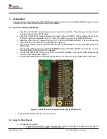
Connect the LMP91000 board to the GPSI16 and AB12 headers. Line up the white arrows at the
bottom of the headers (see Figure 1)
•
Connect the SPIO4 board to its power supply and to your computer via the USB cable in that order.
Figure 1: ADC161S626 Eval board connected to SPIO board.
•
Start the SensorAFE software on your computer.
3.2 Setup for Other Boards
•
Choose the VA supply:
o
Install the VA SELECT jumper between pins 1 and 2 (VA and 5V) to power VA from the 5V
supply coming from the SPIO4 or SPUSI2 board.


