TCP201 User Manual Issue 1.4
Page 29 of 35
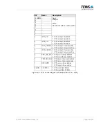
4.2.3 IP Reset Register
The IP Reset Register can be used to initiate an IP RESET cycle and to detect when the IP RESET
cycle has finished. Each IP RESET# signal can be asserted separately.
Writing a 1 to bit 3, 2, 1, or 0 of the IP Reset Register initiates that the reset cycle and the
corresponding IP RESET# signal is asserted. After 200 ms, the on board logic automatically negates
the IP RESET# signal and completes the IP Reset cycle.
The IP Reset Register can be read to verify the IP reset status.
At power-up or board reset, all IP RESET# signals are asserted simultaneously.
Bit
Name
Description
15 (MSB)
-
14 -
13 -
12 -
11 -
10 -
9 -
8 -
7 -
6 -
5 -
4
Read:
Always 0
Write:
No effect, should be written with 0's
3 IPD_RESET
2 IPC_RESET
1 IPB_RESET
0 (LSB)
IPA_RESET
Read: 0 : IP RESET# - signal is de-asserted
1 : IP RESET# - signal is asserted
Write: 0 : No effect
1 : Assert corresponding IP RESET# - signal
(automatic negation after 200 ms)
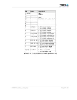
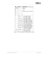
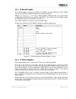
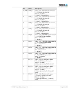
Figure 4-11: IP Reset Register (PCI Base Address 2 + 0x0A)
4.2.4 IP Status Register
The IP Status Register can be used to read IP timeout, error and interrupt status.
An IP timeout occurs if the IP module fails to generate the IP ACK# signal within the IP timeout time.
The IP timeout time is app. 8µs. An IP timeout is not reported to the PCI9030 or the PCI master, but in
the IP Status Register. If the corresponding IP_TIME_EN bit in the IP Control Register is set, an
interrupt is generated if a timeout occurs. This interrupt can be cleared by writing ‘1’ to the timeout
status bit. If a timeout occurs during an IP read, all ones (0xFF) are returned.
The IP ERROR# signal is used to indicate component failure, unrecoverable self-test failures or
serious, hard-wired configuration errors. The status of the IP ERROR# signals can be read in the IP
Status Register.
Interrupt status of all IP interrupt lines can read in the IP Status Register. If edge sensitive interrupt is
enabled (see IP Control Register for detail) and an interrupt is active, writing a “1” to bit 7:0 clears the
corresponding interrupt status.


