background image

Before you Install 

Car audio equipment installations can be troublesome at times, even to the 
most experienced of installation technicians. If you are not con

fi

dent working 

with electrical wiring, removing and reinstalling interior panels, carpeting, 
dashboards or other components of your vehicle, please call our customer 
support number 01270 508538 and we will recommend 

fi

tters in your area. 

1.

Remove the outer trim frame. 

Din Front Mount 

2.

Insert the keys supplied with the old 
unit into both sides of the unit as 
shown in 

fi

gure below until they click. 

Pull to remove the old unit from the 
dashboard. 

DO NOT DISCONNECT WIRES 
AT THIS TIME! 

3.

Mark the polarity of the speaker wires. Marking the polarity of the speaker 
wires will make it easier to connect the existing speakers to your car radio. 
Consult wiring diagram of existing head unit before disconnecting any 
wires. If you are not positive of the polarity of the existing wires from the 
speakers to the head unit, install new wires. 

a.

While the old unit is playing, disconnect the wires from one speaker. 

b.

Take a length of masking tape and fold it around the wire so it forms a 

fl

ag. 

c.

On the masking tape mark the polarity of the speaker wires (+ & -), as well as 
left or right and front or rear. 

d.   Double check that you marked the 

fi

rst speaker correctly by checking 

that the speaker wires are the same at the head unit. 

e.      Repeat the procedure for all of the speakers. 
f. 

 Mark the power, ground and any other wires also. 

Summary of Contents for 49180

Page 1: ...D and Front Aux input Now you have purchased a Tevion product you can rest assured in the knowledge that as well as your 3 year parts and labour warranty you have the added peace of mind of dedicated...

Page 2: ...You Install 5 6 Installation 7 8 Wiring Diagram 9 Location of the Controls 10 Basic Operation 11 15 Bluetooth Operation 16 CD MP3 USB SD Operation 17 FAQ 18 Technical Specification 19 Warranty 20 Faul...

Page 3: ...phone our Helpline for immediate assistance Faulty product claims made within the 3 year warranty period will be repaired or replaced free of charge provided that you have satisfactory proof of purcha...

Page 4: ...ased files from for instructions on proper use 4 Never allow children to play with electrical equipment Care of Discs Do not use CDs with labels or stickers attached The label may leave a sticky resid...

Page 5: ...ads to chassis ground The unit is only designed for use with 4 speakers Do not combine output for use with 2 speakers Do not ground negative speaker leads to the chassis ground Make sure all the conne...

Page 6: ...HIS TIME 3 Mark the polarity of the speaker wires Marking the polarity of the speaker wires will make it easier to connect the existing speakers to your car radio Consult wiring diagram of existing he...

Page 7: ...ews from the top of the unit before installing Din Front Mount 1 After removing the old radio and mounting sleeve insert supplied mounting sleeve into opening 2 Bend the tabs on the mounting sleeve to...

Page 8: ...ce screws 4x8mm depending on the shape of the screw holes in the bracket 3 Vehicle factory mounting bracket 4 Dashboard or console 5 Hook remove this part 2 x Keys 1 x Aux in wire 1 x Fascia carry cas...

Page 9: ...ar Right Speaker 2 Rear Right Speaker 3 Front Right Speaker 4 Front Right Speaker 5 Front Left Speaker 6 Front Left Speaker 7 Rear Left Speaker 8 Rear Left Speaker Speaker Wiring Notes Follow the abov...

Page 10: ...slot 20 USB port 21 SD slot 22 Anti theft LED indicator 23 RESET button 1 OPEN button 2 SEL button and VOL dial 3 POWER button 4 LCD 5 6 and button 7 BAND button 8 MODE button 9 MUTE button 10 AP butt...

Page 11: ...econds you are able to cycle through the following options TA ALARM SEEK PI SOUND MUTE RETUNE LONG SHORT MASK DPI ALL BEEP ON OFF USER SET FLAT CLASSIC ROCK POP VOL LAST DEFA MONO STEREO FM MODE ONLY...

Page 12: ...I mode Masks only the AF which has di erent PI MASK ALL mode Masks the AF which has di erent PI and NO RDS signal with high field strength b5 BEEP ON BEEP OFF BEEP ON mode A beep is sounded when any k...

Page 13: ...aker temporarily and press again to resume listening You can also exit mute by using MODE SEL buttons or the VOL dial on the fascia panel 10 AP BUTTON Auto Storage Preset Scan If you press and hold th...

Page 14: ...gress REGIONAL MODE OFF The regional code in the format of PI is ignored when AF switching or PI SEEK is implemented PI CODE and COVERAGE AREA is not checked when AF CHECK is in progress 13 TA TRAFFIC...

Page 15: ...CLK button until the real time flashes on the display you can adjust the time by using the VOL dial and SEL button 16 TEL BUTTON 17 AUX IN For connection of other audio device 18 EJECT BUTTON Before...

Page 16: ...e phone has successfully connected you will see a blue led on the display flashing This LED will turn to solid when you are on a call or disappear when you disconnect from the stereo Dial To make a ca...

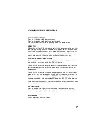
Page 17: ...y to the first song on the disc USB or SD device You can use the INT button to sample the first 10 seconds of each song To activate this feature simply pres the INT button to deactivate this function...

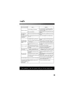
Page 18: ...FAQ S 18 If your problem is not listed please call our customer support team...

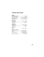
Page 19: ...sions 178 W X 50 H X 165 D FM SECTION Frequency range 87 5MHz 108MHz Usable sensitivity 3uV I F Frequency 10 7MHz AM SECTION Frequency range 522KHz 1620KHz I F Frequency 450KHz Usable Sensitivity 40dB...

Page 20: ......

Reviews: