6
Settings and operation
Activating and deactivating
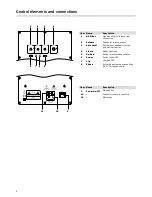
• With the switch
9
“POWER” the subwoofer is activated or
deactivated. When the subwoofer is on, the LED
6
“Power” is
illuminated in
– green, if the subwoofer is in operating mode
– red, if the subwoofer is in standby mode.
Automatic activation/switching to standby mode
• Switch
5
“ON AUTO”:
–
AUTO
position: The subwoofer activates as soon as an
audio signal is present at the input jack
4
“LINE IN”.
If there is no audio signal for 20 minutes, the subwoofer
automatically switches to standby mode.
–
ON
position: The subwoofer is continually activated.
Changing the input sensitivity of the automatic activation
• Using the controller
3
“AUTO LEVEL” you can change the
sensitivity of the automatic activation. This is helpful if the
subwoofer does not activate in spite of a present audio sig-
nal or if it is activated by glitches.
Use a small screw driver for turning the controller.
Volume
• The volume control
2
“VOLUME” is used to control the
subwoofer volume.
Phase
• Using the switch
8
“PHASE” you can activate and deactivate
phase shifting (180°) for the subwoofer. Choose a setting
at which the subwoofer emits the loudest and most precise
sound.
HP-Filter
• With the high-pass filter
1
you can set a value between 30
and 70 Hz. All frequencies, which are lower than this set
value are weakened or completely faded out.
• The filter is intended to adjust the subwoofer to small rooms
in order to avoid potential droning sounds.
Clip
LED
7
“CLIP” is illuminated
• if the subwoofer is overloaded due to an excessive input
signal. Reduce the input signal if this LED lights up.
• if the subwoofer gets too hot. Reduce the volume and check
the unit's ventilation.
• if the power supply is faulty.
Crossover frequency
• The subwoofer must be “On” in the Bass management/
Speaker management (“Speaker Setup”) for the amplifier/AV
receiver. The appropriate crossover frequency to be set there
depends on the satellites being used. You can find specifica-
tions for the crossover frequency of the respective satellites
in the technical data section of our web shop.
1
2
3
4
5
6
7
8
9

