background image

7 testo REXS Testing/Programming GUI 

32


Note: 
All data entered in edit config and edit port are stored and will be recalled if you 
run the GUI the next time. 

Click connect to connect the computer to testo REXS. 
If desired, lock the testo REXS front panel buttons by clicking lock/unlock REXS. 


Note: 
Even if testo REXS is in locked mode, all safety devices (emergency stop button, 
external emergency stop, propane concentration warning) are still fully 
functional. 


Note: 
If testo REXS is in locked mode, a dedicated timer watches over the 
communication. If the communication with the GUI fails, testo REXS switches 
back to unlocked mode and will shut down with an error. 

 
Click the start/stop REXS button and wait until testo REXS has started properly. After successul 
start-up, Testo 

REXS switches to „STBY“ mode, and „STBY“ is displayed on the testo REXS GUI 

display. 
Select the operating point by selecting one of the listed operating points. You also may use the 
UP/DOWN arrows beside the listbox 


Note: 
S

electing operating points different to „STBY“ is only enabled when testo REXS 

is in „RUN“ mode. For more information, refer to the testo REXS manual or quick 
guide. 

 
To shut down testo REXS, click the start/stop REXS button. Wait until testo REXS has shut down 
properly. 
 
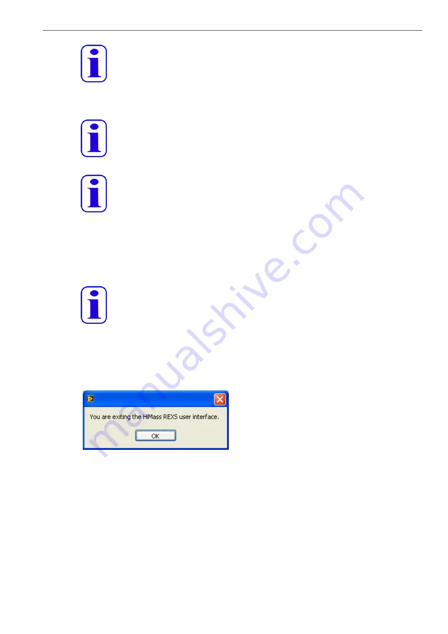
To exit the testo REXS GUI, click exit. A message window is displayed. 


Fig. 7.4: Exit message window 


If you are exiting the software while testo REXS is still running, a window will appear and ask you 
how to proceed: 
• unlock testo REXS and exit the software: unlock testo REXS, if it is locked, do not switch to 
„STBY“ mode or shut down testo REXS, but quit the GUI. 
• shutdown testo REXS and exit the software: shutdown testo REXS and quit the GUI. 
• set testo REXS to standby mode: switch testo REXS to „STBY“ mode. The GUI will remain 
open and running. 
Click OK to confirm the selection, or click Cancel to go back to the GUI without changing the 
actual state. 


Summary of Contents for REXS

Page 1: ...testo REXS User Manual...

Page 2: ...The Benefits Are 9 4 3 Function Principle 9 4 4 The System 9 4 4 1 Soot Generator 10 4 4 2 Input 10 4 4 3 Processing 10 4 4 4 Output 11 4 5 Front Panel Operational Elements 12 4 6 Back Panel Operation...

Page 3: ...f the testo REXS GUI 31 7 7 Errors Troubleshooting 33 7 7 1 Communication Errors 33 7 7 2 Testo REXS Errors 33 8 Appendix 36 8 1 Specification Technical Data 36 8 2 Service Guide 37 8 2 1 Cleaning of...

Page 4: ...of delivery Excluded from the warranty are all parts subjected to normal wear as any fuses batteries or other consumable parts Also excluded are Defects resulting from abnormal use in particular outsi...

Page 5: ...operation by untrained staff any technical modification not carried out by Testo SE Co KGaA or an authorized service partner use of not genuine spare parts The content of this manual is generated with...

Page 6: ...iable operation Listed labels Cautions and Warnings are explained in general and the further specific labels refer to type of hazard and danger Note Note Note means this content describes important us...

Page 7: ...check gas leak tightness Gas filled cylinders Compressed and explosive gas Broken or leak cylinder may destroy the locality and environment Soot Nanoparticles Soot particles hazard When breathed in s...

Page 8: ...this follows that propane C3H8 nitrogen N2 and air are transformed into carbon monoxide CO carbon dioxide CO2 water vapour and soot nanoparticles 4 1 2 Applications Compared to a diesel combustion eng...

Page 9: ...and 100 nm Soot nanoparticles mass output of 1 5 g h at 80 nm Capable to work against back pressure up to 500 mbar Flexible and simple operation Simple test bench integration Local and or remote contr...

Page 10: ...t of the burner Note Oxidation air is feeded internally from quench air in standard setup A separate oxidation air supply may be used if necessary Quench air The quench air is supplied through an enco...

Page 11: ...r carbon dioxide CO2 carbon monoxide CO water vapour and soot particles leaves the combustion chamber at the top of the burner The soot nanoparticle forming process Laminar diffusion flame Since the f...

Page 12: ...erefore to a reliable operation Red indicators refer to an error Description green red dark Flame Flame on Flame not detected Burner off Run Standby Run mode Standby mode Burner off Fuel Gas 1 Propane...

Page 13: ...ion Put back by pushing and also turning right side the button when the problem is resolved Fig 4 5 Warning indicators Warning Explosive gas Propane sensitive safety devices In case of any malfunction...

Page 14: ...s supply connector Electrical power and compressed air connectors Pos Description Connector 1 Mains power plug IEC 60320 C14 plug type 2 Main switch 0 off 1 on 3 Compressed air Legris quick coupling I...

Page 15: ...socket 7 EIA 232 serial communication with PC 9 pin Sub D socket 8 Internal diagnostic for factory only use 25 pin Sub D socket Fig 4 10 Back panel connectors 5 Transportation Unpacking and Extend of...

Page 16: ...ings for international transportation The ISPM15 label and the packaging manufacturer identification code is printed at the front cover of the package 5 2 Unpacking Once the box is in the right place...

Page 17: ...ller or safety devices Do not store the instrument outdoor the storage environment must be dust free and dry Always store testo REXS in the specific wooden packing After long time storage or transport...

Page 18: ...h 7 1 ea R2635 5 pin 18 mm plug X111 testo REXS remote control 8 1 ea R2633 3 pin 18 mm socket X112 external emergency stop 9 1 ea 56113 5 AT spare fuse for F101 control unit 10 1 ea 56113 5 AT spare...

Page 19: ...5 Transportation Unpacking and Extend of Delivery 19 Fig 5 6 testo REXS Fig 5 7 Flanges centering rings and bulkhead rings Fig 5 8 Air hose and power cable Fig 5 9 Flange built up Pos 4 Pos 3...

Page 20: ...run up to 2000 meter above sea level Floor load capacity Floor load capacity has to be 400 kg m2 in minimum Ambient air conditioning Provide enough cool ambient air for convection cooling of the burne...

Page 21: ...ition with easy access to the main valve Always close the main valve first in case of fuel gas alarm or smell of fuel gas Gas supply connections All gases are supplied by supply net or gas cylinder En...

Page 22: ...AC or 110 VAC power supply Refer to the label to determine supply voltage for the instrument Connect the IEC 60320 C13 socket of the power cord to the IEC 60320 C14 plug at the back side of the instru...

Page 23: ...g emitted or not To access these signals open plug X111 Remove the bridge between pin 1 and 2 The test bench control signal RUN closing contact has to be connected to pin 1 and 2 The testo REXS state...

Page 24: ...testo REXS Keep the tubing as short as possible to prevent particle losses caused by diffusion and coagulation Caution Do not restrict the aerosol flow out of the burner The aerosol flow is mass flow...

Page 25: ...REXS burner emits toxic gas CO and CO2 The test bench has to be installed with HEPA backup filter devices Soot Nanoparticles Soot particles hazard testo REXS burner emits soot nanoparticles The test b...

Page 26: ...re may result in pulsation and or aerosol flow oscillation The soot size distribution and concentration may shift Tee and an additional pipe B disposed and if required a supply for the dilution air ad...

Page 27: ...ation 27 Fig 6 2 Direct connection of the testo REXS to the DUT with additional dilution air supply Fig 6 3 Direct connection of the testo REXS to the DUT with additional dilution air supply with volu...

Page 28: ...plorer 6 Memory 256 MB Disk space 30 MB Note testo REXS GUI may run on slower computers but performance is not guaranteed 7 2 Installation Procedure Insert the CD ROM into the CD ROM drive of your com...

Page 29: ...computer and check the available COM ports Memorise the port number of the COM port where you connected the serial cable to your computer 7 5 Controls and Indicators Start the GUI by clicking Start a...

Page 30: ...low is measured in lN min slpm meaning the gas flow at 0 C and 1013 mbar back pres too high red indicator is lit if the back pressure pressure inside the burner is above 500 mbar back pressure display...

Page 31: ...will open and automatically run If the test stand setup has changed click edit config and update the application description Confirm by clicking OK Fig 7 2 Edit configuration window Note All data ente...

Page 32: ...splay Select the operating point by selecting one of the listed operating points You also may use the UP DOWN arrows beside the listbox Note Selecting operating points different to STBY is only enable...

Page 33: ...XS Fig 7 6 Communication error window example If you click OK the GUI will retry to communicate with testo REXS However if the communication fails several times click stop to exit the GUI Locate the e...

Page 34: ...1 MFCA Actual values of all mass flow controllers out of tolerance window 12 ER12 BUPR Burner differential pressure above 500mbar 13 ER13 EMER Stop on emergency 14 ER14 SSP System error caused by sync...

Page 35: ...ss field out of range 130 ERR_RS232_LENRANGE Serial command data length out of range 131 ERR_RS232_FRAMEREAD Serial command framing error while reading 132 ERR_RS232_FRAMEWRIE Serial command framing e...

Page 36: ...r dry 2 relative humidity at 23 C dew point approxi mately 28 C clean 5 m filtered and oil free air up to 1000 lN min at 7 bar Gas interfaces Orange C3H8 encoded quick coupling orange with tube and ex...

Page 37: ...E Safety EN 61010 2001 referring to voltage directive 2006 95 EG EMC conformity emission EN 61326 2006 Class A immunity EN 61000 2001 industrial level EM Safety EN 50371 2002 referring to EMC directiv...

Page 38: ...ark Ignition Electrode To remove the electrode loosen the 3 M4 Torx screws that hold the pneumatic cylinder to the electrode case Use a T20 screw driver Pull out the electrode together with the pneuma...

Page 39: ...meter Inch m cm mm m nm in 1 m 1 100 1 000 1 0 106 1 0 109 39 37 1 cm 0 01 1 10 1 0 10 4 1 0 10 7 0 3937 1 mm 0 001 0 1 1 1 000 1 0 10 6 0 0394 1 m 1 0 10 6 1 0 10 4 1 001 1 1 000 3 937 10 5 1 nm 1 0...

Page 40: ...in 1 639 10 5 0 0164 16 387 1 5 787 10 4 1 cft 0 0283 28 317 2 832 10 4 1728 1 Volumetric flow l min m3 h 1 lN min 1 0 060 1 m3 h 16 667 1 1 lN 1 standard liter at 0 C 1 013 25 hPa Units Length m mete...

Page 41: ......

Page 42: ...Testo SE Co KGaA Testo Strasse 1 79853 Lenzkirch Germany phone 49 7653 681 5062 fax 49 7653 681 95062 e mail sales nanoparticle testo de...

Reviews: