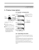
4. Initial operation
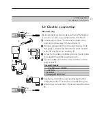
4.2 Electric connection
12
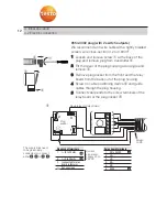
1 2 3 4 5 6
I+
Flexible lead of relay board
Screen
on PE
I-
1
3
2
Plug socket terminals
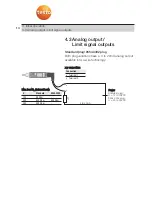
1: I+ (4 to 20mA)
2: I- (4 to 20mA)
3: (connected to relay
board in factory)
: Put on screen
Relay board terminals
1: 20 to 28VDC
2: LS+
3: LS-
4: US+
5: US-
6: 0VDC
Current
signal and
supply 20 to
28VDC
Plug
socket
Relay boar
d
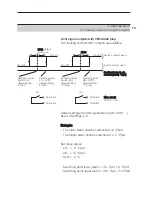
The supply lines need
to be galvanically
connected, so connect
either
-
or -
!
0554.3302 plug (with 2 switch outputs)
We recommend an 8 wire cable with a tightly braided
screen, wire cross-section 0.2 to 0.8mm
2
.
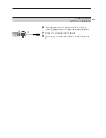
1 Loosen and remove screw
at the back of the
plug and remove plug from transmitter
.
2 Tilt the cover of the plug housing at an angle and
remove
.
3 Remove plug socket from the front and the relay
board from the back out of the plug housing.
4 Screw on cable positioning device
and guide
cables through the plug housing.
5 Connect cable ends to the screw terminals of the
relay board or the plug socket
:
Summary of Contents for 6740
Page 1: ...Instruction manual en testo 6740 ...
Page 28: ...0970 6740 en 08 en GB ...


