background image

22

DIGITAL MULTI METER

Voltage, current, resistance, continuity can be tested.

W A R N I N G

To prevent an electric shock, injury or damage to RAPPORT337, cut
off the power supply of the circuit, and discharge all the high-voltage
capacity before testing resistance and continuity.

When applying the meter function by using your RAPPORT337, make
sure to turn on its power and set up the proper mode before
connecting the test lead set to the circuit to be tested.

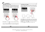
SETUP of KEY SELECT

First, press             button, and then press            button to be changed to

OHM/BUZZ 

First, press

button, and then press

button to be changed to 

ACV/DCV. 

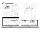
This button is used to test current below 4mA.

This button is used to test current below 400mA.

This button is used to test current below 10A.

21

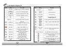
Description of METER MODE LCD WINDOW

Part

Function

Kinds of test to

set up

Test value to

display

Measured value

graph

Measured value

in hold

MODE display

Description

-   Resistance test
-   Continuity test 
-   Set up tests of  DC/AC voltage, current

-  

unit of resistance test is indicated

-   Indicator of AC or DC value of voltage or current
-   AC voltage & current are indicated as rms

(root mean square)

-   Input measured value is indicated in the form of  

graph

Graph is changed automatically equal to the  
measured value in automatic mode

OVER is displayed when higher value is 
measured than the setup value

The measured value is stored and indicated here,
when SET key is pressed at the moment of the
value measured

Digital Multi Meter Mode is displayed

Summary of Contents for Rapport 337

Page 1: ...99 Washington Street Melrose MA 02176 Fax 781 665 0780 TestEquipmentDepot com...

Page 2: ...s of RAPPORT337 6 Standard Items 7 Names Functions of Each Part 8 3 Specifications of Rapport337 13 General Specifications 13 Meter Specifications 14 4 Functional Use 16 Power ON OFF 16 OSD Setup Scre...

Page 3: ...al is for users of Rapport337 Starting with the outline of Rapport337 the manual is emphasized on the explanations of its operation how to be connected to the other devices how to use every button and...

Page 4: ...humidity or leaking gas environments Do not touch it with wet hands Be mindful not to shock or shake the unit while in use to avoid damage Avoid the places of strong magnetism or electric wave which w...

Page 5: ...Analyzer It determins which protocol to control your PTZ Camera from PTZ Controller or DVR This will guide CCTV installer to understand the Protocol and find the fault device easily UPT Cable tester...

Page 6: ...hecklist below placing them on a level place Rapport337 Main Body User s Manual Test Lead Set Red Black Adapter Rechargeable AA Size Nickel Hydrogen Ni MH Battery 6EA Necklace UTP test Terminal BNC Vi...

Page 7: ...being charged Red LED is on when data is transmitted Red LED is on when data is received TFT LCD Part Name Function Key Button METER PART Test Lead Connection Test Lead Positioning for Lead Connectio...

Page 8: ...ly generated Video Test Signals It is the port of input output of communication signal Rx Rx Tx Tx It braces Rapport337 It hangs on the neck for safety It hangs on the neck for safety Part Name UTP Ja...

Page 9: ...ocol support 2400bps 38400bps RS 422 RS 485 direct cross cable and broken or short circuit can be tested Charging Time Operation time Above 8 hrs More than 4 hrs W 88mm X L 190mm X T 58mm max Meter Sp...

Page 10: ...with a beep Release the button The power goes off A rechargeable battery should be plugged in over 8 hrs for full charge The charged battery can operate for 4 hrs or so When the battery indicator sho...

Page 11: ...right left for PTZ is made and zooming manual focus are adjusted UTP Cable Tester mode UTP cable direct cross cable disconnection and short circuit are tested 17 View Information mode At this mode the...

Page 12: ...when key is pressed And it returns to the initial setup value when one of the two keys is pressed for more than 3 sec C Indicates screen sharpness and the brightness increases gradually by 1 when key...

Page 13: ...rent below 4mA This button is used to test current below 400mA This button is used to test current below 10A 21 Description of METER MODE LCD WINDOW Part Function Kinds of test to set up Test value to...

Page 14: ...to beep at below 80 How to measure Connect the red lead to and the black lead to as shown in the figure above at left and measure the resistance directly at the resistance measuring mode by pressing...

Page 15: ...int and the black lead on point each on the voltage source MEASURING AC DC CURRENT Current is simply defined as a flow of electrons running through a conductor To measure current you must break the ci...

Page 16: ...ected there may occur burnout of fuses damage or breakdown of the system when the voltage is measured 27 PTZ CONTROLLER How to connect each terminal and LCD screen PTZ Operation Test The basic operati...

Page 17: ...ized location 29 The controlling code of protocol from the key board or DVR is displayed on the screen Most important however is that the communications speed should be of one accord SPST It memorizes...

Page 18: ...Setup of PTZ PROTOCOL The initial setup is made PELCO D and changing to PELCO D PELCO P and WONWOO are available in accordance with the protocol mode of PTZ It is done by pressing keys 31 BAUDRATE Se...

Page 19: ...NFORMATION Mode Setup First press key more than 3 sec and select VIEW INFORMATION on MODE SELECT MENU then press key MAIN SETTING Mode Setup First press key more than 3 sec and select MAIN SETTING on...

Reviews: