Tescom CL115D Series User Manual Download Page 31


27 

F9 DC BUS ???? 
Before PFC start, DC bus voltage is lower than 50 volts DC. PFC stage is no allowed to start. 
 
F10 BOOSTER SOFT 
Booster soft start step could not be completed within 16 seconds 
 
F11 DC BUS ERROR 
DC bus voltage is lower than PFC start minimum limit. PFC system can not start. 
 
F12 SHORT CIRC. 
There is a short circuit at the output of the UPS. Disconnect loads one by one and try to reset UPS. 
 
F13 WAVEFORM 
A63 INV.FAILURE alarm occurred 4 times within 60 minutes. Unstable waveform error. 
 
F14 BATT.SAMPLE? 
Battery voltage control signal is lost or signal level is wrong. 
F15 4-INV FAIL


Inverter output low or high alarm has occurred 4 times within 1 hour. Inverter output voltage is out of tolerance. 
 
F16 4-OVERCURR.


 Overcurrent has been sensed in UPS 4 times within 1 hour.


F17 MIS-FUNCTION 
Maintenance bypass switch is suddenly turned on without switching to manual bypass first. 
 
F18 ALT.PROTECT. 
The inverter sinus waveform alternance is longer than expected. 
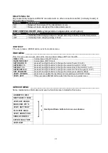
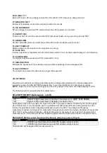


ADJUST MENU 
 
Adjust menu contains some factory selectable options, settings and adjustments. A service password is 
required,to access the ADJUST MENU.please refer to your local distributor for changing your options. 
NOTE : adjust menu is only for service purpose. the wrong usage of this menu can cause damage to UPS. 
 
The following options are selectable from adjust menu : 
 

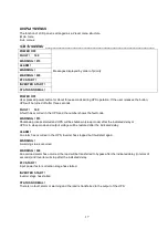
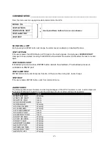
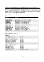
SPLIT BYP:ON /OFF (Split bypass : on/off) 

OPTION 

DESCRIPTION 

ON 

Bypass voltage measurement enabled in measures menu. (BYP.: 230V 50.0Hz) 

OFF 

Bypass voltage measurement disabled in measures menu. 

Split bypass input is the secondary AC input to the UPS. This input is used for transferring the load to bypass. 
As a default, there is no split bypass input on a standard CL115D series UPS. But during production in the 
factory, it is possible to install a separate split bypass input to the UPS. The voltage and frequency 
measurement system is ready and the measurement inputs are shorted to the already available AC input of the 
UPS. If OFF option is selected bypass voltage and frequency measurement  menu item will be cleared from 
measures menu. If ON option is selected, separate bypass measurements will be shown in measures menu. 
 
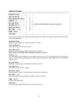
REPO INPUT:NO/NC contact (function of the Remote emergency power off input) 

OPTION 

DESCRIPTION 

NO 

If REPO input terminals are shorted UPS applies emergency stop 

NC 

If REPO input terminals are opened UPS applies emergency stop 

This selection will be applied after the next power on. 


Summary of Contents for CL115D Series

Page 1: ...UPS USER MANUAL CL115D...

Page 2: ...detailed instructions on how to use and install the product For information on how to use your equipment to its full potential this manual should be kept close at hand beside the UPS and PLEASE READ...

Page 3: ...EARTH 12 III OPERATION 13 DESCRIPTION 13 PROTECTIONS INSIDE THE UPS 13 PRELIMINARY OPERATIONS 13 POWERING ON FOR THE FIRST TIME 14 Switching On Normal Operation The UPS From Off Position 14 Switching...

Page 4: ...AGKK9530 01 2011...

Page 5: ...le power supply UPS in an energy backup system provides secure protection against any possible faults in the AC power system DESCRIPTION OF THE FUNCTIONS OF THE CL115D UPS CL115D UPS is a DSP micropro...

Page 6: ...nt limit on or off selectable o Output fuse protection o PID control in output voltage regulation o Isolated short circuit protection from bypass input o Adjustable output voltage low and high protect...

Page 7: ...duces an overtemperature alarm The measured cabinet inside temperature is also displayed on the panel and used for changing the battery charging voltage to compensate for the temperature changes Block...

Page 8: ...If input power is connected risk of electric shock is valid The unit is powered by more than one power source AC input power DC battery power even when it is in MAINTENANCE BYPASS position WARNING Si...

Page 9: ...on Rear view of the UPS 4 Emergency Stop 5 SNMP Socket 6 RS232 communication port 7 Cooling outlet of the UPS 8 Output switch fuse S1 9 Input switch fuse S2 10 Battery switch fuse S3 11 Maintenance by...

Page 10: ...larms are shown one after the other as time shared II INSTALLATION ALL THE OPERATIONS DESCRIBED IN THIS SECTION MUST BE CARRIED OUT EXCLUSIVELY BY QUALIFIED TECHNICIANS The company may no be held liab...

Page 11: ...rs should be made with the cables provided or in any case with shielded cables less than three meters long INSTALLATION ENVIRONMENT When choosing the site in which to install the UPS the following poi...

Page 12: ...he rear and front side No objects should be left on its top surface Sufficient space should be left in front of the equipment for it to be turned on off and maintenance operations to be performed on i...

Page 13: ...gulations Before making power connections to the unit ensure that the incoming power sources are de energized and insulated The connections of the UPS should be supplied by grounded outlets All contro...

Page 14: ...ication connector of the CL100D series UPS is a D type 9 pins female type connector This connector contains dry contact relay outputs and RS232 data pins together All dry contact pins and RS232 data p...

Page 15: ...1 Remove the metal guard on the input output terminal group and connect phase neutral and earth input cables During connection match phase cable to phase input neutral cable to neutral input earth cab...

Page 16: ...n the system and also the earthing and neutral bonding arrangements should be in accordance with the local laws Proper grounding considerably reduces problems in systems caused by electromagnetic inte...

Page 17: ...00 125 load UPS operates for 10 minutes then transfers the load to bypass adjustable time 126 150 load UPS operates for 1 minute then transfers the load to bypass adjustable time If the load is greate...

Page 18: ...l wait and see the UPS control panel is activated and displays some messages Note that during start up bypass lamp red is turned on indicating that bypass voltage is available on the output terminals...

Page 19: ...nd press ENTER button the load will be transferred to bypass without interruption After transfer the message will be changed to ENT START Transferring the load to maintenance bypass from On Normal Ope...

Page 20: ...ng of the alarm message on the second line is the standard alarm code for a particular alarm condition The remaining message part can be different in each language but the alarm code is always the sam...

Page 21: ...the number shows the fault code WARNING 015 Shutdown process started and UPS will be shutdown sleep mode after the indicated delay or UPS is in sleep mode and output voltage will be restored after th...

Page 22: ...e and bypass input frequency in Hertz This submenu is available only if split bypass option is selected LOAD CF 1 4 Load crest factor measurement For linear loads the crest factor is 1 4 for nonlinear...

Page 23: ...r key during this message UPS will clear all recorded events from memory Note For log table clearing service password is required Otherwise the user can not clear log events In this case LOG CLEAR FOR...

Page 24: ...REMOTE CONTROL FROM RS232 on off This option enables or disables the remote control of UPS through its serial port OPTION DESCRIPTION ON The control options of UPS is enabled from serial port login r...

Page 25: ...k DATE 10 01 2007 Current date of RTC clock SET HOURS 13 press left and right buttons to change the current hours 0 to 23 SET MINS 15 press left and right buttons to change the current minutes 1 to 59...

Page 26: ...ome other messages may be shown in this menu sub item These are message description B TEST DISABLED By some reason battery test function is off PERFO TEST 250 V UPS is performing battery test and the...

Page 27: ...hutdown process is controlled via RS232 port ENT LAMP TEST ENTER button starts panel lamps test function At the same time during test buzzer beeps ENT EXIT If the user presses ENTER button exits from...

Page 28: ...justable the load is higher than 125 Or during the last 600 seconds adjustable the load is higher than 100 A10 LINE FAILURE Mains voltage is lower than the allowed minimum AC voltage level or a blacko...

Page 29: ...early warning about battery charger events Normal battery high alarm system level is quite high and it gives warning possibly after some damage to batteries has occurred Average voltage system gives...

Page 30: ...S system blocked load on bypass F12 SHORT CIRC 145 UPS system blocked load shutdown F13 WAVEFORM 146 UPS system blocked load on bypass F14 BATT SAMPLE 147 UPS system blocked load on bypass F15 4 INV F...

Page 31: ...ease refer to your local distributor for changing your options NOTE adjust menu is only for service purpose the wrong usage of this menu can cause damage to UPS The following options are selectable fr...

Page 32: ...Relay activates if load is greater than 100 RLX BATT TEST Relay activates if battery test is being performed RLX OVERTEMP Relay activates if cabinet inside temperature is high RLX BATT FUSE Relay act...

Page 33: ...CTS Dry contact outputs for some major events SNMP connection Available Optional Modbus connection Over TCP IP or over RS485 available optional RS232 hardware Baud rate 2400 baud Connection 3 wire RX...

Page 34: ...232 commands or not If off option is selected the incoming commands from RS232 will be cancelled For adjustment parameters you must type the service password from front panel otherwise any adjustment...

Page 35: ...synchronization Adjustable between 1 0 and 3 0 Hz RFI Level EN62040 Split By pass Connection OPTIONAL Input power connections Hardwired from the rear Maintenance bypass switch OPTIONAL OUTPUT Number...

Page 36: ...high protection standard Cold start from batteries standard Battery temperature compansiation standard INTERFACE RS 232 comm Port Standard RS 485 comm Port OPTIONAL Remote Monitoring Panel OPTIONAL SN...

Page 37: ...33...

Page 38: ...34 AGKK9530 06 2014...

Reviews: