5
8
Device information table
This shows the data of module:
“Device model”: model of the module.
“Serial number”: serial number of the module.
“Software version”: module software version number.
“Hardware version”: module hardware version number.
“FPGA version”: module FPGA firmware version number.
“IP 1”: IP address of the control interface.
“IP 2”: IP address of the streaming interface.
“System time”: current time, synchronized from the time source set in the “System menu”→ “Date Time” submenu, see
section 7.6.8.
“Up time”: time passed from last power-up or restart of the module.
In the "Common status" table the following parameters are displayed at real time: internal temperature in degrees of
Celsius, processor load in percentages, power voltage in Volts, output bit rate in Mbps.
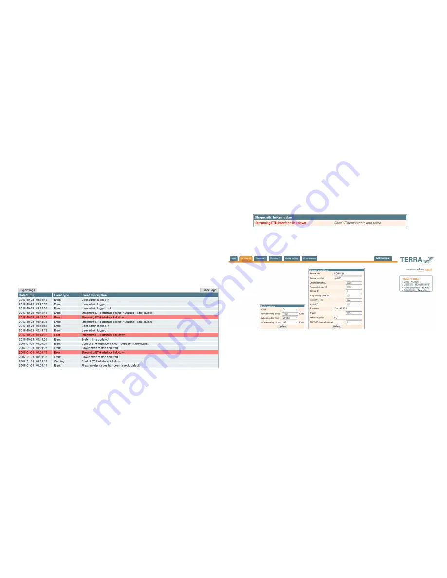
In the "Diagnostic information" table all module errors and comments how to eliminate these errors are displayed.
Figure 8. Diagnostic information table with errors
7.3 Encoder #1-3
This screen consists of two tables with appropriate encoder media settings and streaming settings.
Figure 9. "Encoder #1-3" screen
7.3.1. Media settings table
The "Media settings" table consists of following parameters:
"Active" – used to enable/disable the appropriate encoder. When the “Active” parameter is set to “Off”, all rest parameters
in table are disabled.
"Video encoding bitrate" - the bitrate of H.264 encoded video stream in Kbps. Can be set in the range 1000 – 11500 Kbps.
For the best quality of encoded video stream it is recommended to set bitrate at maximum.
"Audio encoding type" – used to select between MPEG2 or AAC audio encoding standard.
"Audio bit rate” - the bitrate of encoded audio stream in Kbps. Can be set in the range 32 – 320 Kbps.
Once the different data values have been entered, click on “Update” to conclude the media settings.
7.3.2. Streaming settings table
The "Streaming settings" table consists of following parameters:
“Service title”- enter a service name of the output stream.
"Service provider" - enter a provider name of the output stream.
“Original network ID” - enter a unique identifier of a broadcast platform operator.
“Transport stream ID” - enter an identifier of a TS within an original network.
“Service ID” - enter an indentifier which serves as a label to identify this service from any other service within the TS.
“Program map table PID” - a Program map table (PMT) identifies and indicates the locations of the streams that make up
each service and the location of the Program Clock Reference fields for a service. Enter a packet identifier (PID) of PMT.
7.5.2. SNMP settings table
The description of the "SNMP settings" table rows.
"Enable TRAP" - SNMP traps are alerts generated by agents on a managed device. Check this box to enable TRAP
generation. The streamer generates traps when the diagnostic message occurs.
“Trap community”, "Read community" - community name acts as a password that is shared by multiple SNMP agents
and one or more SNMP managers. The "Read Community" password is used for read-only access to encoder parameters.
"Write Community" - is the password used for read-write access to encoder parameters.
"TRAP Community" - is the password used for accessing of TRAPS.
"Trap IP address 1-3" - IP addresses of hosts with SNMP managers, where TRAPS will be send.
7.5.3. E-mail settings table
The device can send e-mail reports if errors were detected. SMTP protocol is used for that. “E-mail-settings table” shows
parameters related to this feature. “Enable e-mail error report” checkbox enables error monitoring. All errors within “timeout”
period will be gathered, and send to the e-mail address, provided in “Receiver e-mail address” input box. Comma separated
e-mail addresses can be used to send report to multiple addresses. The timer will be started as soon, as the first error is
detected, and stopped when e-mail is sent. The timer will be restarted again if a new error will appear. “Sender e-mail address”
can be used as authentication in the SMTP server side. SSL (SMTPS) protocol is not supported.
7.6. System menu
This menu tab contains following submenu items: “Event logs”, “Export parameters”, “Import parameters”, “Firmware
upgrade”, “User management”, “Restore defaults“, “ Reset the device“, “Time, Date”, “Language”. Mouse over to show the
list of this submenu.
7.6.1. Event logs
Various important events, errors, warnings will be logged into the system, see Figure 13 "Event logs". Each record has
an event type, which can be used to filter particular messages. Just select checkboxes in the „Logs filtering“ table and press
„Apply“. Other messages will be hidden.
„Erase logs“ button will erase all logs from the system.
“Export logs” button forms the file (log.html) which will be downloaded to PC.
Each record has a log time when the event appeared. Refer to 7.6.8 "Date and time settings" for instructions how to
configure time settings.
Figure 13. Event logs
7.6.2. Export parameters
All settings of encoder can be exported for backup or copying to another device. Press “Export parameters” and
“parameters.xml” file will be downloaded to PC. This file can be imported only to the same type of device.
7.6.3. Import parameters
Exported parameters can be imported back to the device. Press onto “Click to select file” button (see Figure 14 "Import
parameters") to select exported file.


