background image

11

2

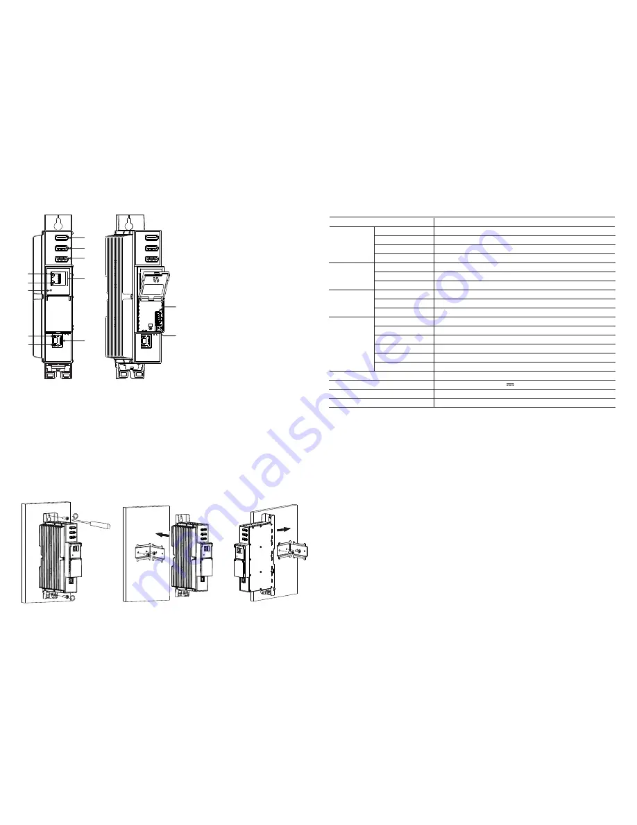
5. Installation instructions

Read the safety instruction first.

All settings can be made using the web browser via control Ethernet interface. 

Disconnect power supply unit from the mains before make all connections of modules.

Mount  the  module  on  DIN  RAIL  or  individual  holder. The  module  or  mounting  bracket  must  be  fixed  with  steel  

screws Ø 3.5-4 mm. The screws are not included in a package.

Connect all necessary HDMI, powering and control cables. Shielded cable is recommended for Ethernet connection.

Connect power supply in to the mains.

Within 5-20 seconds of powering the module will run in normal operation mode.

Comments of the Ethernet interface indicators:

•   if the link with the control Ethernet interface is established - the LINK/ACTIVITY indicator [5] blinks;

•   when module operating, the STATUS indicator [6] blinks at frequency about one time per second;

•   if the link with the streaming Ethernet interface is established - the LINK indicator [12] glows.

1, 2, 3

  - 

HDMI 1

HDMI 2

HDM 3

 input connectors.

4


ETHERNET

 - control over Ethernet interface. 

RJ-45 socket.

5


- LINK/ACTIVITY (yellow) indicator of the Ethernet 

interface.

6

 - STATUS (green) indicator.

7

 - 

RESET

 button. 

* Press this button shortly to restart the module. 
* Press this button for more than three seconds to 
set the default IP address of control over Ethernet 
interface. Administrator password will be changed 
to the default value as well.

8

 - Power distribution bus connector.

9

 - +12 V DC powering input. Screw terminal.

10

 - 

TS/IP OUT

 - streaming Ethernet interface. 

RJ45 socket.

11

 - ACTIVITY (yellow) indicator of the streaming 

Ethernet interface.

12

 - LINK (green) indicator of the Ethernet interface.

4. External view 

6. MOUNTING
Mounting on a wall by screws 

Mounting on a bracket (supplied)

Figure 1. External view of the encoder


Perpendicular to the wall 

Parallel to the wall 


Figure 2. Mounting of the encoder

Technical specifications

Type


mhi430


Video input


input signal type HDMI


video coding 

MPEG-4 AVC/H.264, Baseline profile 4.0


input resolution


1920x1080-60p

 output resolution


1920x1080-30p

Audio input


input signal type


HDMI


standard


MPEG-1 Layer II, AAC


audio bit rate


64, 96, 128, 192, 256, 320, 384 kbps

H.264 Encoder 

standard 

MPEG-4 AVC/H.264


bit rate 

4 - 11  Mb/s  adjustable


configurable parameters 

Service Name, Service ID, Video PID, Audio PID, PMT PID, PCR PID

IP output


standard


IEE802.3 10/100 Base T


bit rate  

up to 100 Mbps


transmission protocols 

UDP/RTP


multicast


Yes


MPTS No


SPTS Yes

Supply voltage 


12 V ±1 V

Current consumption   

700 mA  max.

Operating temperature


0

C


÷


+50

C

Dimensions/Weight (packed

)


48.5x198x112 mm/0.9 kg

DC IN 

12V

-  

+

mhi430

RESET

ETHERNET

TERRA

1
2

5
6

4

7

8

9

TS/IP

OUT

10

11

12

HDMI  1

HDMI 2

HDMI 3

3

mhi430

DC IN 

12V

-  

+

TS/IP

OUT

HDMI  1

HDMI 2

HDMI 3

Summary of Contents for mhi430

Page 1: ...as central heating components or in areas of high humidity Keep the module away from naked flames If the module has been kept in cold conditions for a long time bringing it into a warm environment may cause condensation so allow it to warm up for no less than 2 hours before plugging into the mains Ventilation should not be impeded by covering the module such as newspapers table cloths curtains etc...

Page 2: ...o set the default IP address of control over Ethernet interface Administrator password will be changed to the default value as well 8 Power distribution bus connector 9 12 V DC powering input Screw terminal 10 TS IP OUT streaming Ethernet interface RJ45 socket 11 ACTIVITY yellow indicator of the streaming Ethernet interface 12 LINK green indicator of the Ethernet interface 4 External view 6 MOUNTI...

Page 3: ...ged To restore IP address and system password to system defaults see RESET button at section 3 pos 7 Several seconds can take to restore all parameters so be patient 7 6 7 Restart the device Device will be restarted after confirmation to do it This is an alternative to pressing a RESET button when the device is operating 7 6 8 Date Time System time can be configured manually or taken from NTP serv...

Page 4: ...creen you will see a main menu tabs 1 Using it you can switch between the different configuration menus The tab highlighted in yellow shows which menu is active at a given moment The System menu tab contains several submenu Also common elements for all screens is module title 2 and login information strings 3 The module title can be changed after pressing the Change button in the Device informatio...

Page 5: ...ID of PMT 7 5 2 SNMP settings table The description of the SNMP settings table rows Enable TRAP SNMP traps are alerts generated by agents on a managed device Check this box to enable TRAP generation The streamer generates traps when the diagnostic message occurs Trap community Read community community name acts as a password that is shared by multiple SNMP agents and one or more SNMP managers The ...

Page 6: ...ty video 3 Low priority video 4 Video and voice 5 Best effort best effort made to correctly deliver the video data and the associated audio data Count of output streams count of output streams displayed in the Output streams table bellow Can be selected from one to twenty five After updating ot the FR input parameters this count is automatically set to input stream count value Send IGMP query mess...

Reviews: