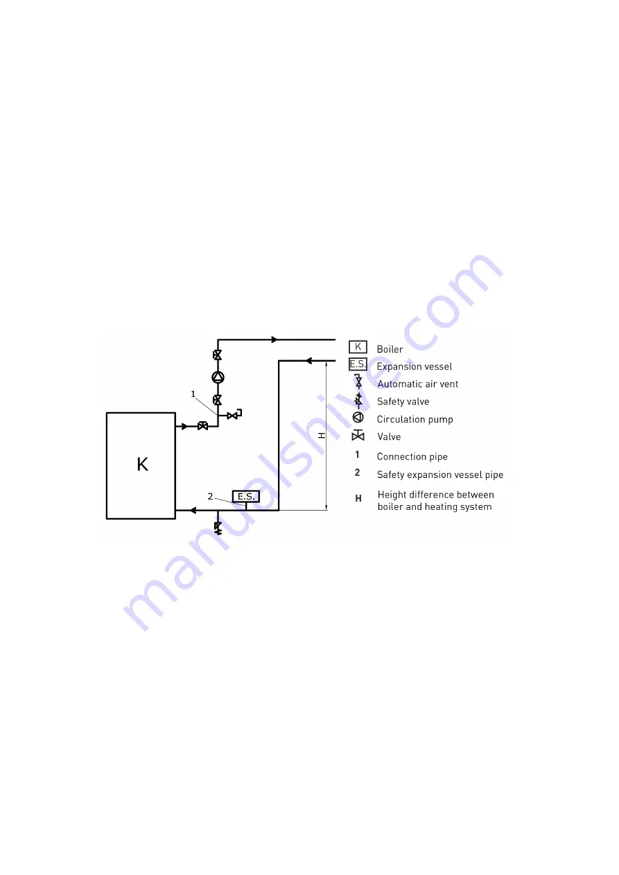
Great care must be taken to ensure air does not enter the boiler.
4.1.2
Installation method 2
To be used in the case of the boiler being positioned and installed at a lower level than the installed
pipe-work and radiators.
As shown on Figure, following elements are connected along the FLOW:
1. Automatic air vent
2. Safety valve
3. Circulation pump (separated with ball valves on each side so that it can be easily replaced if
necessary).
For safe operation info on additional equipment such as expansion vessel and safety valve please refer
to manuals to be delivered with such products.
This air vent valve must be open when first filling the boiler on installation completion.
4.2
Fitting the boiler to an open central heating system.
The connecting scheme of an open central heating system is depicted on the figure.
Open expansion vessel is connected to the hot-water distribution pipes (FLOW and RETURN) as
shown on Figure – with an additional OVERFLOW pipe output plus CIRCULATION pipe (to prevent
freeze during winter months).
Please note that no additional items shall be connected to the open expansion vessel – especially not
valves.
The size of expansion vessel is deducted from the following equation:
V
= 0
,
07
V
water
(
l
)
V
water
(
l
)
is the water volume in the entire installation.
Open expansion vessel is to be positioned vertically above the highest heating element. Both flow an
return line connecting the open expansion vessel must be insulated (40 mm thickness). if the expansion
vessel is outside the heating area, the vessel itself should be insulated.
7


