Service and Repair Manual
December 2018
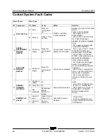
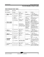
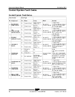
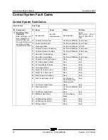
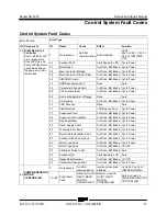
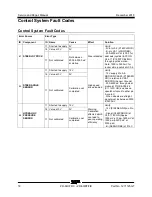
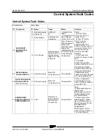
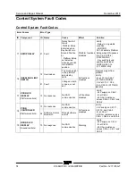
Control System Fault Codes
64
Z®-60/37 DC • Z®-60
/37 FE
Part No. 1271125GT
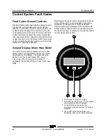
Fault Codes Ground Controls
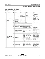
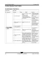
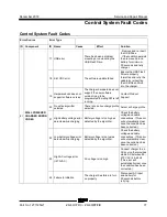
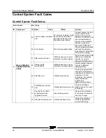
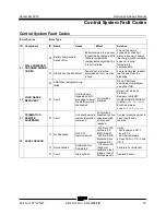
Standard Genie fault codes shall be displayed and
the red LED will illuminate when any faults are
present. If more than one fault code is present, the
codes shall be displayed in succession with each
code displayed for 4 seconds. Once all active fault
codes have been displayed the screen will pause
for 4 seconds and then repeat the list of active fault
codes. Use the
Control Systems Fault Codes
chart
to aid in troubleshooting the machine by pinpointing
the area or component affected.
Ground Display Smart Hour Meter
The smart hour meter will display unit hours and
battery state of charge (SOC) whenever no faults
are present on the system. The value will cycle
between unit hours and battery SOC every
5 seconds. When the engine is running (if
equipped), the display will cycle hours, SOC, and
RPM.
Both Engine Hours and DC Function Enable Hours
will be tracked. DC Function enable hours will be
displayed on the smart hour meter by default.
Engine Hours will be displayed if the hybrid mode
select switch is held for three (3) seconds. Engine
Hours will continue to display as long as the hybrid
mode select switch is held.
1 LCD screen (8 character display)
2 Red LED below the wrench icon illuminates
when system faults are displayed
3 Yellow LED below the battery icon
illuminates when battery state of charge is
displayed.
4 Green LED below the hourglass icon
illuminates when unit hours are displayed.
Summary of Contents for Genie Z-60 DC
Page 54: ...Service and Repair Manual December 2018 Manifolds 44 Z 60 37 DC Z 60 37 FE Part No 1271125GT ...
Page 56: ...Service and Repair Manual December 2018 Manifolds 46 Z 60 37 DC Z 60 37 FE Part No 1271125GT ...
Page 107: ...December 2018 Service and Repair Manual 97 Wiring Diagram Options ...
Page 110: ...Service and Repair Manual December 2018 100 Schematics Options 4WD DC and FE Models ...
Page 111: ...December 2018 Service and Repair Manual 101 Power Cable Wiring Diagram ...
Page 113: ...December 2018 Service and Repair Manual 103 Hydraulic Schematic DC and FE Models ...
Page 115: ...December 2018 Service and Repair Manual 105 Electrical Schematic DC FE Models ...
Page 118: ...Service and Repair Manual December 2018 108 Electrical Schematic DC FE Models ...
Page 120: ...Service and Repair Manual December 2018 110 Electrical Schematic DC FE Models ...
Page 125: ......

