background image

Document 57.0009.0427

47

GTH-4017EX  GTH-4514EX  GTH-4013EX

November 2008

Section 4 - Maintenance Procedures

TABLE


D

D-5  CHANGE THE HYDRAULIC OIL FILTER 

CARTRIDGE (GTH-4013EX)

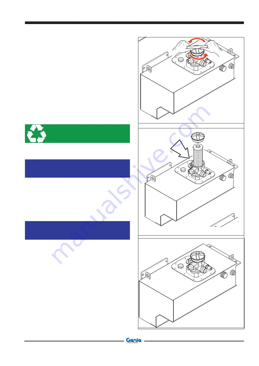
To change the hydraulic oil filter element, proceed as 
follows (GTH-4013EX):
-  Stop the machine on a level ground and engage the 

parking brake.

-  Place a container of suitable size under the filter to 

collect any oil leaks.

-  Remove the filter cover 

to check the cartridge

 C

.

-  Change the filter element 

C

, then, before fitting a 

new one, thoroughly clean and grease both seat and 
gasket.

-  Refit and tighten the filter cover.

PROTECT THE

ENVIRONMENT

Handling and disposing of used oils may be ruled by 
local or national regulations. Address to authorised 
waste centres.

NOTICE

Hydraulic oil filter canisters cannot be cleaned or 
washed and refitted.
They must be replaced with new ones of the type 
recommended by the manufacturer:
Flow rate l/1’ = 150
Filtering = 10 

π

Attachment = 1” 1/4 BSP

NOTICE

When changing the oil, drain it when it is still hot and 
the polluting substances are in suspension.

C

Summary of Contents for 19266

Page 1: ...English Service Manual GTH 4017 EX GTH 4514 EX Serial number range From serial n 19296 From serial n 19286 GTH 4013 EX From serial n 19266 Part No 57 0009 0427 November 2008...

Page 2: ...Document 57 0009 0427 GTH 4017EX GTH 4514EX GTH 4013EX ii Intentionally blank page Service Manual November 2008...

Page 3: ...and equipment Intheseinstances westronglyrecommendlettingservice and repair the machine at an authorized TEREXLIFT service center Technical Publications No part of this publication may be reproduced s...

Page 4: ...READ YOUR SERIAL NUMBER Chassis serial number The chassis serial number is punched on the front left part of the chassis side member GTH 4017 P 07 19296 MODEL ENGINE TYPE YEAR OF MANUFACTURER SERIAL...

Page 5: ...1D110 model 5 The max displacement of this bent axis motor is 80 cm3 rev The motor is directly flanged to the Dana single speed reduction gear 26 which is fixed with brackets to the central zone of th...

Page 6: ...circular chamber of the cylinder 21 there is a pressure relief valve set at 200 bar which limits the load when the boom is extended in those working zones where the electronic overturning control syst...

Page 7: ...axle can oscillate thus making the machine drive more comfortable even in case of rough terrains The chambers of the cylinder are always kept filled with oil by a single hydraulic line connected to t...

Page 8: ...tch activating pressure 10 bar 20 Pressure switch activating pressure 10 bar 20 Hydraulically powered service emergency brakes pedal pump Boom functions hydraulic circuit test port T P A B Mechanical...

Page 9: ...nfoos 51D080 model 5 The max displacement of this bent axis motor is 80 cm3 rev The motor is directly flanged to the Dana single speed reduction gear 26 which is fixed with brackets to the central zon...

Page 10: ...o proportional type with electrical feed back and integrated electronics On the control line of the circular chamber of the cylinders 21 and 40 there is a pressure relief valve set at 230 bar which li...

Page 11: ...the oil circulating freely from to the two chambers of the cylinder In this way the axle can oscillate thus making the machine drive more comfortable even in case of rough terrains The chambers of the...

Page 12: ...ssure 35 bar Pressure switch activating pressure 70 bar Hydraulically powered service emergency brakes pedal pump Boom functions hydraulic circuit test port Hydrostatic transmission motor max displace...

Page 13: ...jury Many of the hazards identified in the Operator s Manual are also safety hazards when maintenace and repair procedures are performed Do Not Perform Maintenace Unless You are trained and qualified...

Page 14: ...involve your own as well as the others safety and that can result in serious or lethal injury DANGER Draws the attention to situations that involve your own as well as the others safety and that can...

Page 15: ...n and free of debris thatcouldgetintomachinecomponentsand cause damage Be sure that your workshop or work area is properly ventilated and well lit Be sure any forklift overhead crane or other lifting...

Page 16: ...e questions if you are in doubt Contact GENIE the assistance service is at your disposal Addresses phone and fax numbers are given in the cover and in the title page of this manual 1 3 SERVICEMEN S RE...

Page 17: ...they could hinder the machine movements and represent a danger for personnel 1 4 2 PRECAUTIONS DURING WORK Do not walk or stop under raised loads or machine parts supported by hydraulic cylinders or...

Page 18: ...your fingers to check for pressure leaks Fine jets of air oil or fuel can injure you Neither smoke nor use open flames if there is a risk of fire or close to fuel oil or batteries Do not leave fuel c...

Page 19: ...on 1 2 1 Main dimensions 1 2 2 Tyres 2 2 3 Limit of use 2 2 4 Weight 2 2 5 Speed 2 2 6 Payload and reach 2 2 7 Forks floating type 3 2 8 Diesel engine 3 2 9 Hydraulic system 3 2 10 Electrical system 3...

Page 20: ...pment of the machine 16 A 14 Check the efficency of the lighting electric system 17 A 15 Check the efficency of braking system 18 A 16 Check the efficency of the steering selection system 19 A 17 Chec...

Page 21: ...ge of the engine air filter GTH 4017EX GTH 4514EX 49 D 8 Change the engine oil filter and the fuel filter 50 D 9 Clean the cab air filter 50 D 10 Change the oil of the front and rear differential gear...

Page 22: ...oom extension cylinder GTH 4017EX GTH 4514EX 21 007 Cylinder disassembly Boom extension external cylinder GTH 4013EX 23 008 Cylinder disassembly Boom extension internal cylinder GTH 4013EX 25 009 Wate...

Page 23: ...80 780 E Track mm 1980 1980 1920 F Wheelbase mm 2850 2850 2950 G Lenght to the front tyres mm 4700 4650 4790 H Lenght to the attachment holding plate mm 6490 6100 6060 I Ground clerance center mm 425...

Page 24: ...900 shovel 800It SAE J732 80 7900 shovel 800It SAE J732 80 6000 shovel 800It SAE J732 80 Chassis levelling 8 8 6 TELELIFT 3512 401 2 6 PAYLOAD AND REACH GTH 4017 EX GTH 4514 EX GTH 4013 EX Lifting hei...

Page 25: ...00 4 400 4 400 Cylinder arrangement vertical in line vertical in line vertical in line Combustion system direct injection direct injection direct injection Max power output 2200 rpm kW 74 5 74 5 74 5...

Page 26: ...0 Front differential gear with reduction gear l 8 7 8 7 8 7 Rear differential gear l 8 7 8 7 8 7 Front wheel reduction gears l 0 75 0 75 0 75 Rear wheel reduction gears l 0 75 0 75 0 75 Engine coolant...

Page 27: ...SIZE THREAD in lbs N m in lbs N m in lbs N m in lbs N m in lbs N m 20 80 9 100 11 3 110 12 4 140 15 8 130 14 7 28 90 10 1 120 13 5 120 13 5 160 18 140 15 8 ft lbs N m ft lbs N m ft lbs N m ft lbs N m...

Page 28: ...0 2 Moderate Excellent Loctite 573 Formed in place gasket 150 0 2 Slow Excellent Loctite 574 Formed in place gasket 150 0 5 Rapid Excellent Loctite 510 Formed in place gasket 200 0 2 Moderate Excelle...

Page 29: ...ILY be handled with suitable hoisting means In the Disassembly and Assembly section there is a clear indication of the weight of the part to handle while chapter A 12 contains a summary table with the...

Page 30: ...reaching the connecting point to the line NO YES YES NO YES YES NO NO YES NO Useful advice for mounting flexible hoses 2 17 ADVICE TO RENEW FLEXIBLE HOSES PROTECT THE ENVIRONMENT Before disconnecting...

Page 31: ...94 Valve 1 04 4210 0008 Female quick coupling 1 04 4210 0007 Male quick coupling 1 54 0001 0058 Lock attachment cylinder pin 1 07 4529 0107 Lock attachment cylinder gaskets kit 1 54 0001 0059 Lock att...

Page 32: ...cover 1 07 0703 0431 Fog light switch 1 07 0703 0435 Air conditioning switch 1 07 0703 0572 Emergency light switch 1 07 0703 0029 Starter switch 1 07 0703 0494 Emergency pump switch 1 07 0703 0430 Me...

Page 33: ...07 0740 0202 Mirror 1 07 0740 0248 Rear windscreen wiper brush 1 07 0740 0054 Stop belt 1 07 0740 0050 External door handle 1 07 0740 0051 Inside door lock 1 07 0740 0029 Inside upper door handle 1 0...

Page 34: ...9 4605 0012 Plug 1 53 3000 8100 Engine smoke manifold 1 09 0803 0259 Guard 0 65 m 07 0712 0012 Insulator 1 07 4529 0031 Gaskets kit 1 07 0700 0000 Hydraulic oil filter cartridge 1 09 4604 0000 Hydraul...

Page 35: ...INE PAINT COLOUR GENIE machine BLU GENIE GREY GENIE BLACK RAL 9500 RED RAL 3002 RAL 2002 RAL 3020 YELLOW RAL 1003 RAL 1018 RAL 1007 RAL 1021 RAL 1016 RAL 1028 ORANGE RAL 2009 RAL 2011 RAL 2004 GREEN R...

Page 36: ...ax engine speed 2 20 CHECKING THE CYLINDER MOVEMENT TIMES CAUTION To check the engine speed the area easy to reach is the shaft of the CASAPPA pump Min engine speed 950 rpm Max engine speed 2600 rpm L...

Page 37: ...6 GTH 4013 EX Time s Up Down Max engine speed 6 8 GTH 4017 EX Time s right to left left to right Max engine speed 8 9 GTH 4514 EX Time s right to left left to right Max engine speed 8 9 GTH 4013 EX T...

Page 38: ...et the pressure control valve A to 280 bar by adjusting the adjustment screw To check the set of the extension boom safety valve see annex 1 proceed as follow With the engine running at maximum speed...

Page 39: ...cab Press down on the service brake by left foot Set the forward or reverse speed Run the engine at maximum speed With engine at minimum rpm on M4 the value of manometer is equal to the value of boos...

Page 40: ...hnical Specification November 2008 TECHNICAL SPECIFICATION Document 57 0009 0427 GTH 4017EX GTH 4514EX GTH 4013EX 18 HYDRAULIC SYSTEM CONTROL MAIN VALVE annex 1 A B T B 2 B T B A 2 GTH 4514EX GTH 4017...

Page 41: ...ember 2008 Section 2 Technical Specification TECHNICAL SPECIFICATION Document 57 0009 0427 19 GTH 4017EX GTH 4514EX GTH 4013EX annex 2 HYDRAULIC SYSTEM OUTRIGGERS L V L V GTH 4514EX GTH 4017EX GTH 401...

Page 42: ...Section 2 Technical Specification November 2008 TECHNICAL SPECIFICATION Document 57 0009 0427 GTH 4017EX GTH 4514EX GTH 4013EX 20 HYDRAULIC SYSTEM TRANSMISSION PUMP annex 3 TP3 TP2...

Page 43: ...November 2008 Section 2 Technical Specification TECHNICAL SPECIFICATION Document 57 0009 0427 21 GTH 4017EX GTH 4514EX GTH 4013EX annex 4 HYDRAULIC SYSTEM TRANSMISSION PUMP B A C D E D F 48 48 M4 M5...

Page 44: ...Section 2 Technical Specification November 2008 TECHNICAL SPECIFICATION Document 57 0009 0427 GTH 4017EX GTH 4514EX GTH 4013EX 22 HYDRAULIC SYSTEM POWER STEERING annex 5 X A Z...

Page 45: ...November 2008 Section 2 Technical Specification TECHNICAL SPECIFICATION Document 57 0009 0427 23 GTH 4017EX GTH 4514EX GTH 4013EX annex 6 HYDRAULIC SYSTEM TRANSMISSION ENGINE M4 B XB A XA...

Page 46: ...1 strain cage 2 washer 10 3 fixing screw M10x40 cl 10 9 A To avoid damaging strain cage and to get maximum results proceed as follows 1 PREPARATION Thoroughly clean whole tightening system especially...

Page 47: ...R CONN X1 MV 282107 1 MV 282089 1 MV 282089 1 MV 282107 1 MV DT068P MV 770680 1 CODE SHLD BLACK REF2 BLUE IN2 GREEN OUT2 RED IN2 WHITE REF2 SHLD BLACK REF1 BLUE IN1 GREEN OUT1 YELLOW OUT1 RED IN1 WHIT...

Page 48: ...entered The access code currently used is 1001 Therefore you should enter the following sequence 1 0 0 1 CONFIRM If the sequence is correct the confirmation of the instrument functioning in the calib...

Page 49: ...part of the wheels to the center of the load see the diagram inside the cab Press to confirm the LOADED calibration of the machine and check that the alarm triggers The audible alarm will sound to con...

Page 50: ...mber 2008 TECHNICAL SPECIFICATION Document 57 0009 0427 GTH 4017EX GTH 4514EX GTH 4013EX 28 LOAD DIAGRAM GTH 4013 EX ON OUTRIGGERS LOAD DIAGRAM GTH 4013 EX ON TYRES LOAD DIAGRAM GTH 4017 EX ON OUTRIGG...

Page 51: ...ovember 2008 Section 2 Technical Specification TECHNICAL SPECIFICATION Document 57 0009 0427 29 GTH 4017EX GTH 4514EX GTH 4013EX LOAD DIAGRAM GTH 4514 EX ON OUTRIGGERS LOAD DIAGRAM GTH 4514 EX ON TYRE...

Page 52: ...l be active if the nacelle is not installed LED4 ON if the interlock relay is active machine safe without alarms D Software version existing in the DLE unit this function allows you to see the softwar...

Page 53: ...outputs do not deactivate Switch off and on the machine and run a complete test of the outputs If the alarm persists replace the DLE Alarm code 9 Description CELL1 and CELL2 reading correspondence Fro...

Page 54: ...Celle_MaxDelta Max admissible delta between readings of analog channels 1 and 2 expressed as a default 10 current 20 11 SpanForche Limiter intervention percentage in case of work with stabilised machi...

Page 55: ...ion with loaded machine 22 C2NavicellaVuoto Value saved in analog channel 2 during calibration with empty machine 23 C2NavicellaCarico Value saved in analog channel 2 during calibration with loaded ma...

Page 56: ...sequence The access code actually used is 1001 Therefore you shall input the following sequence 1 0 0 1 CONFIRM If the sequence is correct the LED next to comes on with a solid light to confirm the pr...

Page 57: ...ows of system image 1 Proceed as follows FILE OPEN Choose the diagnostic file image 1 Select and click INVIO Click on to open the dialog windows image 2 Check the installed SOFTWARE is right image 3 S...

Page 58: ...Section 2 Technical Specification November 2008 TECHNICAL SPECIFICATION Document 57 0009 0427 GTH 4017EX GTH 4514EX GTH 4013EX 36 4 4 4 4 6 5...

Page 59: ...the list of errors at page 39 in the FAULT TABLE A Select PARAMETERS FUNCTIONS to check the parameters Select Allparameters V168 8 Press F2 to ensure the present parameters are uploaded on the control...

Page 60: ...alue 1 see image 11 PRESS F4 Inside the window calibrate inch Potentiometer select the value 0 see image 11 PRESS F4 select the Setup Status menu see image 12 The system recognizes the calibration min...

Page 61: ...of the check transmission control unit Image 16 functional scheme of the transmission The following elements are not used in the present system Creeper drive Creeper drive switch PPU motor Brake press...

Page 62: ...Section 2 Technical Specification November 2008 TECHNICAL SPECIFICATION Document 57 0009 0427 GTH 4017EX GTH 4514EX GTH 4013EX 40 16...

Page 63: ...intenance of this machine Scheduled maintenance must be carried out at the intervals indicated in the MAINTENANCE REPORT WARNING Failure to properly complete each inspection when required may cause de...

Page 64: ...A Weekly A B Monthly A B C Every 2 months A B C D Every 6 months A B C D E Yearly A B C D E F Every 5 years afterwards every 2 years G Maintenance table The maintenance table contains general informa...

Page 65: ...eck and clean the air suction filter A 9 Check and clean the radiator A 10 Check the hydraulic oil level in the tank A 11 Check the greasing of the boom section pads A 12 Grease the forks A 13 Grease...

Page 66: ...e oil level in the front and rear differential gears C 4 Check the oil level in the four wheel reduction gears C 5 Check the main filtering element of the engine air filter Replace if necessary C 6 Ch...

Page 67: ...tridge of the engine air filter D 8 Change the engine oil filter and fuel filter every 500 working hours or once an year D 9 Clean the air filter in the cab D 10 Change the oil in the differential gea...

Page 68: ...pection Selecttheappropriatechecklist s forthe type of inspection to be performed Every 10 hours A Every 50 hours A B Every 250 hours A B C Every 500 hours A B C D Every 1000 hours A B C D E Every 200...

Page 69: ...urs G Place a check in the appropriate box after each inspection procedure is completed Use the maintenance tables in this sectionandthestep by stepprocedures in section 4 to learn how to perform thes...

Page 70: ...Section 3 Maintenance Inspections November 2008 MAINTENANCE INSPECTIONS Document 57 0009 0427 GTH 4017EX GTH 4514EX GTH 4013EX 8 Intentionally blank page...

Page 71: ...RT WARNING Failure to properly complete each inspection when required may cause death serious injury or substantial machine damage Immediately tag and remove from service a da maged or malfunctioning...

Page 72: ...as well as the others safety and that can result in serious or lethal injury WARNING Draws the attention either to situations that involve your own as well as the others safety and that can result in...

Page 73: ...plug all around then remove it and check if oil is level with the hole If necessary add new oil through hole A until it is level Refit the plug PROTECT THE ENVIRONMENT Place a container of suitable si...

Page 74: ...Re tighten all nuts to a torque 440 Nm WARNING Checkthetighteningofwheelsonehourafterthejob They might get loose until they do not stay correct WARNING On new machines and when a wheel has been disass...

Page 75: ...nal Dimensions front rear 405 70 R20 405 70 R24 405 70 R20 405 70 R24 Load Index 14 pr 14 pr 14 pr 14 pr Rim 13x20 13X24 13x20 13X24 Wheel disc 8 holes DIN 70361 8 fori DIN 70361 8 holes DIN 70361 8 f...

Page 76: ...D NUTS Before starting your daily work proceed with a random check of the bolts For the correct tightening torques please refer to par 2 13 in section 2 Technical Specifications A 4 CHECK THE COUPLING...

Page 77: ...ble and in good condition always return the manual to the storage container after use NOTICE ContactGENIEServiceCentreifreplacementmanuals are needed A 6 INSPECT THE DECALS AND PLATES Maintaining all...

Page 78: ...op the machine on a level ground stop the engine and ensure the parking brake is engaged Pull out the rod of the level A and ensure the oil comes to the maximum height B MAX MAX MIN Pull out the rod A...

Page 79: ...B Extract the external filtering cartridge C Clean the inside of the filter Knockoutthefilteringcartridgeusingawoodenboard to eliminate the dust Dry clean the cartridge max pressure 6 bar Check for c...

Page 80: ...Extract the external filtering cartridge C Clean the inside of the filter Knockoutthefilteringcartridgeusingawoodenboard to eliminate the dust Dry clean the cartridge max pressure 6 bar Check for cra...

Page 81: ...m Cleaning using compressed air Direct a jet of compressed air toward radiator paying attention not to damage its fins Remove any loose particles of dirt with some water Cleaning using water under pre...

Page 82: ...to detect oil leaks Check visually the hydraulic oil level through level A on the tank visible through a hole on the right side of the chassis If necessary add oil through plug B WARNING Check the oil...

Page 83: ...s located on the four sides of the profile These pads are secured to both fixed and mobile part of every section At regular intervals check that the telescopes are well greased in correspondence of th...

Page 84: ...Section 4 Maintenance Procedures November 2008 TABLE A Document 57 0009 0427 GTH 4017EX GTH 4514EX GTH 4013EX 14 CHECK THE GREASING OF THE BOOM SECTION PADS GTH 4017 EX...

Page 85: ...thoroughly clean the intervention zone to avoid that mud dust or other matters can mix with the lubricant and reduce or annihilate the lubrication effect Remove any old grease with a degreaser from th...

Page 86: ...or other matters can mix with the lubricant and reduce or annihilate the lubrication effect Remove any old grease with a degreaser from the telescopes before smearing them with new grease Regularly g...

Page 87: ...must be replaced use the table below as a reference WARNING When switched on lamps get hot Before touching a lamp with your fingers let it cool down CAUTION Never touch the bulb of halogen lamps with...

Page 88: ...surface of about 15 8 5 If possible use a oscillating axle Engage the parking brake Check the parking brake with the forward or reverse gear put and ensure the machine is stopped 2 CHECK SERVICE BRAKE...

Page 89: ...right or to the left 4 Setthesteeringselectionswitchto two wheelsteer pos 0 5 Rotate the steering up to its stop turn in the same direction as above 6 Reset the steering selection switch to four whee...

Page 90: ...e machine s forks To check the efficiency of the fork balancing system obey the instructions below Drive the machine to a flat smooth ground Move the retracted boom fully down and align the forks with...

Page 91: ...top pushbutton at every use To check the efficency of the emergency stop pushbutton A push it during one of movement operations of the machine the operation and the machine engine has to stop Check of...

Page 92: ...a limit switch is faulty or a lever is deformed immediately replace the part Check of the limit switches at every use Limit switches C on boom Lift the boom over the zero position until a maximum ang...

Page 93: ...ng brake at every use To check the efficency of the limit switches on the parking brake follow the procedure below Sit in the driving seat engage the parking brake and make sure the machine does not m...

Page 94: ...tection gloves and keep your face at a safe distance Every week before starting working with the coolant cold check the coolant level through the glass cap of plug B When necessary add clean water or...

Page 95: ...buzzer sounds an error code is shown on the display 2 and the machine enters the alarm mode and cannot be operated The meaning of the error messages is shown in Section 2 To do a manual check it will...

Page 96: ...s should retract fully Then hold the system over relief for approx 20 40 seconds to change the hydraulic oil inside the system If after performing this procedure the boom still remains out of sequence...

Page 97: ...in efficient working order NOTICE Fortheenginemaintenance pleaserefertothespecific Operator s manual supplied with the machine B 2 CHECK THE TENSION OF THE ALTERNATOR BELT Open the carter with engine...

Page 98: ...e table below On new machines and when a wheel has been disasembled or replaced check the nut torque of the wheels every 2 hours until they stay correct Torque 400 N m WARNING Always use tyres having...

Page 99: ...le and fit the 8 nuts Tighten the nuts following the alternate sequence shown in the picture using a pneumatic screwdriving machine Lower the machine to the ground Re tighten all nuts to a torque 400...

Page 100: ...Maintenance Procedures November 2008 TABLE B B 5 CHECK THE TIGHTENING OF THE CARDAN SHAFT SCREWS Check every week that the screws of the Cardan shaft A B are tight For the correct tightening torques...

Page 101: ...pressure or steam Cleaning using compressed air Direct a jet of compressed air toward radiator paying attention not to damage its fins Remove any loose particles of dirt with some water Cleaning usin...

Page 102: ...rom the reduction entirely Rotate the wheel by 90 until the plug is on the hori zontal axis Add the oil through hole A Refit the plug A Recommended oil TRACTORENAULT THFI 208 LF SAE 80W API GL 4 FORD...

Page 103: ...d the oil through the plug A until it is level with hole Refit the plug A Recommended oil TRACTORENAULT THFI 208 LF SAE 80W API GL 4 FORD M2C 86 B Massey Ferguson M 1135 C 2 CHANGE THE ENGINE OIL AND...

Page 104: ...until oil comes out from the hole A Refit the plugs A e B PROTECT THE ENVIRONMENT Place a container of suitable size under the plug for oil leaks C 4 CHECK THE OIL LEVEL IN THE FOUR WHEEL REDUCTION GE...

Page 105: ...er B Pull out the filter cartridge C Clean the filter bowl Knockthecartridgeusingawoodentabletoeliminate the dust Dry clean the cartridge at max 6 bar pressure Check the filter element for cracks Refi...

Page 106: ...ve the cover B Pull out the filter cartridge C Clean the filter bowl Knockthecartridgeusingawoodentabletoeliminate the dust Dry clean the cartridge at max 6 bar pressure Check the filter element for c...

Page 107: ...eep out of items which can produce sparks of naked flames or lit cigarettes Do not rest metal objects onto the battery This can result in a dangerous short especially during a recharge C 7 CHECK THE A...

Page 108: ...For this operation fully extend all of the cylinders and check that their rods are intact C 9 CHECK THE HYDRAULIC LINES Every month do a random check of the oil dynamic hoses to be sure they are not w...

Page 109: ...ged CAUTION Replace any worn cables immediately before using the machine again A A A C 11 CHECK THE WEAR OF THE SLIDING PADS OF THE BOOM SECTIONS Any boom section is fitted with adjustable pads locate...

Page 110: ...th or without slots Fit the necessary amount of shims If the residual thickness of the pad is insufficient or near the maximum wearing limit renew the pad Tighten the screws fixing the pads at the rec...

Page 111: ...OF THE BOOM SECTIONS Check every month that the telescopes are well greased in correspondence of the sliding pads If necessary scrape off the old grease and apply a thin film of new grease Use only G...

Page 112: ...battery leads since they can short the terminals and burn you DANGER Beforedisconnectingthebattery setallswitches within the cab to OFF Todisconnectthebattery disconnectthenegative lead from the frame...

Page 113: ...lescope extensioncylindermovetheboomtomaximumheight and extend it some centimetres Loosen the oil hoses to the cylinder of which you are checking the valve with caution Tochecktheefficentworkingordero...

Page 114: ...action generated does not result in an uncontrolled movement of the machine TO REMOVE THE BLOCK VALVES OR THE CYLINDERS Lower the boom to the ground in a firm way since the removal of the block valve...

Page 115: ...ount of smoke coming out of the exhaust is normal repeat the check while accelerating the engine CAUTION Do this check outdoors or use an adequate smoke extraction system NOTICE In case of excess smok...

Page 116: ...are tight For this operation use a torque wrench and tighten the screws to a torque of 288 Nm D 4 CHECK THE BLACKLASH BETWEEN PINS AND BUSHINGS IN ALL JOINTS Every 6 months check the machine randomly...

Page 117: ...the cartridge C Change the filter element C then before fitting a new one thoroughly clean and grease both seat and gasket Refit and tighten the filter cover PROTECT THE ENVIRONMENT Handling and dispo...

Page 118: ...and engage the parking brake Place a container of suitable size under the filter to collect any oil leaks Close the gate A Remove the filter cover B Change the filter element then before fitting a new...

Page 119: ...e warning lamp on the cab dashboard switches on replace the outer element WARNING Do not wash the cartridge using water or other kind of solvents A B C B C CHANGE THE MAIN CARTRIDGE OF THE ENGINE AIR...

Page 120: ...th a new one Add new oil through the plug A Using the rod C check the right engine oil level Remove the fuel filter E and change it with a new one B A C D E D 9 CLEAN THE CAB AIR FILTER Clean the air...

Page 121: ...on the contrary repeat the procedure Lock the chain tensioners by means of a counternut and locknut Change the chains if during the procedure described above all threaded part of the screws have been...

Page 122: ...er element should be replaced every second time the outer element is replaced WARNING Do not wash the cartridge using water or other kind of solvents A B C D CHANGE THE SAFETY ELEMENT AIR FILTER GTH 4...

Page 123: ...it and tighten A Recommended oil TRACTORENAULT THFI 208 LF SAE 80W API GL 4 FORD M2C 86 B Massey Ferguson M 1135 E 3 CHANGE THE OIL IN THE FOUR WHEEL REDUCTION GEARS To change the oil in the four whee...

Page 124: ...e container Using a 13 mm combination wrench remove the screws of the inspection cover D and then remove it Carefully wash the tank with Diesel oil and blow a jet of compressed air Change the inner ca...

Page 125: ...he plug A Using a screwdriver loosen the clamp and remove the rubber hose B Allow the coolant to flow out into a special container Refit the hose and pour new antifreeze 50 water antifreeze in the plu...

Page 126: ...CHECK THE MACHINE STRUCTURE Five years after the first placing into operation of the machine or after 6000 hours whichever occurs first check the state of the structure paying attention to the welded...

Page 127: ...ting instructions printed in the Operator Manual of the machine Be sure that all necessary tools are available and ready for use Read each appropriate flow chart thoroughly Pay special attention to th...

Page 128: ...calandhydraulicpartsindicatedin the following tables are given to help you find such parts on the schemes and diagrams in chapter 6 The tables should be read as follows once you have identified the pr...

Page 129: ...damaged Checkthatthegroundbraidbetween chassis and engine is correctly connected and intact Check the fuse in the box inside the engine compartment replace if necessary Check that contact 30 of the ig...

Page 130: ...ed Check the fuse and replace if necessary Check the wiring for continuity Check the starting motor coil is powered If the coil is powered and the motor doesn t work change the motor Check and replace...

Page 131: ...e mechanical operation of the limit switches replace if necessary Check the fuse replace if necessary Check you have 12V on solenoid when the forward gear is put and 12V on solenoid when the reverse g...

Page 132: ...ace if necessary Check the wiring for continuity Check the socket and replace if necessary Change the DLE Check the fuse replace if necessary Check the spools and replace if necessary Check that the s...

Page 133: ...and replace if necessary Check the wiring for continuity Check the fuse and replace if necessary Check the switch and replace if necessary Check the fan motor and replace if necessary Check the wiring...

Page 134: ...ring line Check the pressure switch and replace if necessary Check the indicator light and replace the lights group if necessary Check the wiring for continuity Check the efficiency of the bulb and re...

Page 135: ...heck the hour meter and replace if necessary Check the alternator and replace if necessary Check the wiring for continuity Check the fuse and replace if necessary Change the DLE Check the wiring for c...

Page 136: ...clean tank and pipes empty the pumps and add new oil Re calibrate the pump see par 2 section Technical Specifications Check the coil and the movement of the inner electrovalve pin Tension the cables...

Page 137: ...of the hydraulic drive and if the pilot activates the priority valve Check the efficiency and the internal seals of the cylinders The pump doesn t deliver oil Check the max output pressure of the pump...

Page 138: ...telescope extension Block valve of the boom internal extension cylinder damaged only GTH 4013 EX Blockvalveoftheboomexternalextension cylinder damaged Check the pump thoroughly Check the efficiency o...

Page 139: ...reaches the max working pressure see par 2 section Technical Specifications Check the efficiency of the internal sliders of the main valve Check the boom In case of mechanical jamming rectify Check an...

Page 140: ...ged Check the efficiency of the safety valves fitted to ports A and B of the module re calibrate or replace Remove and clean the valve check its seal and replace if necessary Remove and clean the valv...

Page 141: ...control with spring Mechanical control with roller Electro magnetic control with winding solendoid Control with electric motor M Direct pressure control Indirect piloted pressure control Control with...

Page 142: ...TING ELEMENTS Three way and two position distributor with hydraulic control Electro hydraulic single acting servo valve Distributor with mechanical control and span proportional to the action of the s...

Page 143: ...0 5 Litri precharge pressure 50 bar capacity 0 5 Litri precharge pressure 50 bar capacity 1 5 Litri precharge pressure 35 bar Pressure switch activating pressure 70 bar Pressure switch activating pre...

Page 144: ...piloting ratio 4 1 R1 T1 T1 T2 T2 R2 T A P B capacity 0 5 Litri precharge pressure 50 bar capacity 0 5 Litri precharge pressure 35 bar Pressure switch activating pressure 70 bar Hydraulically powered...

Page 145: ...AND RELAYS Relay Battery ACCUMULATORS Thermocouple Element Ring TERMINALS AND GROUNDS Ground Terminal Ground to frame Knot Protection ground Frame ground 2 Coil COILS Mechanical coupling coil Winding...

Page 146: ...4514EX GTH 4013EX 6 Thermal CONTACTS Normally open NO Normally closed NC NO limit switch NC limit switch Contactor Magneto thermal closure Thermal closure Thermal opening Exchange NC proximity NO prox...

Page 147: ...November 2008 Section 6 Schemes SCHEMES Document 57 0009 0427 7 GTH 4017EX GTH 4514EX GTH 4013EX 6 4 ELECTRICAL SCHEMES 6 4 1 GTH 4013EX 1 11...

Page 148: ...Section 6 Schemes November 2008 SCHEMES Document 57 0009 0427 GTH 4017EX GTH 4514EX GTH 4013EX 8 2 11...

Page 149: ...November 2008 Section 6 Schemes SCHEMES Document 57 0009 0427 9 GTH 4017EX GTH 4514EX GTH 4013EX 3 11...

Page 150: ...Section 6 Schemes November 2008 SCHEMES Document 57 0009 0427 GTH 4017EX GTH 4514EX GTH 4013EX 10 4 11...

Page 151: ...November 2008 Section 6 Schemes SCHEMES Document 57 0009 0427 11 GTH 4017EX GTH 4514EX GTH 4013EX 5 11...

Page 152: ...Section 6 Schemes November 2008 SCHEMES Document 57 0009 0427 GTH 4017EX GTH 4514EX GTH 4013EX 12 6 11...

Page 153: ...November 2008 Section 6 Schemes SCHEMES Document 57 0009 0427 13 GTH 4017EX GTH 4514EX GTH 4013EX 7 11...

Page 154: ...Section 6 Schemes November 2008 SCHEMES Document 57 0009 0427 GTH 4017EX GTH 4514EX GTH 4013EX 14 8 11...

Page 155: ...November 2008 Section 6 Schemes SCHEMES Document 57 0009 0427 15 GTH 4017EX GTH 4514EX GTH 4013EX 9 11...

Page 156: ...Section 6 Schemes November 2008 SCHEMES Document 57 0009 0427 GTH 4017EX GTH 4514EX GTH 4013EX 16 10 11...

Page 157: ...November 2008 Section 6 Schemes SCHEMES Document 57 0009 0427 17 GTH 4017EX GTH 4514EX GTH 4013EX 11 11 6 4 1 1 FUSES AND RELAYS GTH 4013EX...

Page 158: ...Section 6 Schemes November 2008 SCHEMES Document 57 0009 0427 GTH 4017EX GTH 4514EX GTH 4013EX 18 6 4 2 GTH 4017EX GTH 4514EX 1 11...

Page 159: ...November 2008 Section 6 Schemes SCHEMES Document 57 0009 0427 19 GTH 4017EX GTH 4514EX GTH 4013EX 2 11...

Page 160: ...Section 6 Schemes November 2008 SCHEMES Document 57 0009 0427 GTH 4017EX GTH 4514EX GTH 4013EX 20 3 11...

Page 161: ...November 2008 Section 6 Schemes SCHEMES Document 57 0009 0427 21 GTH 4017EX GTH 4514EX GTH 4013EX 4 11...

Page 162: ...Section 6 Schemes November 2008 SCHEMES Document 57 0009 0427 GTH 4017EX GTH 4514EX GTH 4013EX 22 5 11...

Page 163: ...November 2008 Section 6 Schemes SCHEMES Document 57 0009 0427 23 GTH 4017EX GTH 4514EX GTH 4013EX 6 11...

Page 164: ...Section 6 Schemes November 2008 SCHEMES Document 57 0009 0427 GTH 4017EX GTH 4514EX GTH 4013EX 24 7 11...

Page 165: ...November 2008 Section 6 Schemes SCHEMES Document 57 0009 0427 25 GTH 4017EX GTH 4514EX GTH 4013EX 8 11...

Page 166: ...Section 6 Schemes November 2008 SCHEMES Document 57 0009 0427 GTH 4017EX GTH 4514EX GTH 4013EX 26 9 11...

Page 167: ...November 2008 Section 6 Schemes SCHEMES Document 57 0009 0427 27 GTH 4017EX GTH 4514EX GTH 4013EX 10 11...

Page 168: ...Section 6 Schemes November 2008 SCHEMES Document 57 0009 0427 GTH 4017EX GTH 4514EX GTH 4013EX 28 11 11 6 4 2 2 FUSES AND RELAYS GTH 4017 EX GTH 4514 EX...

Page 169: ...il return filter 5 Drive motor 6 Combined engine fluid hydraulic oil radiator 7 Front axle 8 Hydraulic oil tank 9 Rear axle 10 Hydraulic steering 11 Steering selection solenoid valve 12 Brake pump 13...

Page 170: ...Section 6 Schemes November 2008 SCHEMES Document 57 0009 0427 GTH 4017EX GTH 4514EX GTH 4013EX 30 8 4 5 11 21 14 18 17 20 22 10 15 13 19...

Page 171: ...November 2008 Section 6 Schemes SCHEMES Document 57 0009 0427 31 GTH 4017EX GTH 4514EX GTH 4013EX 6 1 2 3 16 7 12 9...

Page 172: ...Section 6 Schemes November 2008 SCHEMES Document 57 0009 0427 GTH 4017EX GTH 4514EX GTH 4013EX 32 Intentionally blank page...

Page 173: ...der 1 0 30 change the cylinder inside the boom GTH 4013EX 2 2 50 cad change the cylinder inside the boom kit GTH 4013EX 1 1 30 change the block valve of the extension cylinder inside the boom GTH 4013...

Page 174: ...e for the fork locking 1 3 00 change the boom pads 1 3 00 check the transmission pump pressure 2 1 00 cad check the main valve pressure of the boom movement control 2 1 00 cad check the brake pump pre...

Page 175: ...30 change the maxi fuses and search for troubles 1 0 30 bleed the braking system 2 0 30 cad change the return filter of the hydraulic oil tank 1 0 30 change the hydrostatic steering unit 1 1 30 change...

Page 176: ...Section 7 Repair Procedures November 2008 REPAIR PROCEDURES Document 57 0009 0427 GTH 4017EX GTH 4514EX GTH 4013 EX 4 Intentionally blank page...

Page 177: ...e the boom to max height the hinging pin of the cylinder rod must be over the driving cabin operating alternately the bridge crane and the hydraulic boom raising control of the machine 4 Stop raising...

Page 178: ...up down controls of the bridge crane previously disconnect the rod of the fork balance cylinder 8 Remove the screw fixing the pitching cylinder pin with two 13 mm wrenches 9 Knock out and extract the...

Page 179: ...ches 13 Knock out and extract the pin using a plug of soft material aluminium copper wood etc 14 Put two wooden plugs each 100mm high on the oil tank to support the raising cylinder 15 Lower the boom...

Page 180: ...pin using a plug of soft material aluminium copper wood etc and extract it through the hole on the frame 19 Lower the boom onto the adjustable stand to remove the slinging chains 20 Sling the cylinder...

Page 181: ...514EX GTH 4013 EX 2 Cylinder disassembly Fork balance cylinder Bridge crane payload 500 kg Textile bridles or chains with hooks Standard tools Adjustable stands 26 2 1 Operation 1 Release the attachme...

Page 182: ...THE ENVIRONMENT Used oils must be handled and disposed of according to local regulations Address to legally authorised centres 6 Using a 24 mm and a 19 mm wrenches disconnect three hydraulic hoses fr...

Page 183: ...two 13mm wrenches remove the two screws of the spring A 4 Again with two 13mm wrenches loosen the five screws B that secure the cover to the frame of the machine 5 Remove the upper cover 6 Disconnect...

Page 184: ...e engine and namely d oil pressure bulb d electrical stop d water temperature bulb d the three alternator connections d starter motor d ground between chassis and engine d the two coils of the transmi...

Page 185: ...pump with a 36mm wrench d disconnect the suction line of the hydraulic pump with a 50mm wrench d disconnect the low pressure line duct with a 19mm wrench d disconnect the four flanges which connect t...

Page 186: ...wo on the front and two at the back of the vibration damping brackets with a 22 mm wrench 19 Sling the engine using a two leg chain with hook to be coupled to the two top lugs 20 Raise the engine with...

Page 187: ...gthehydraulicpiping place containersofsuitablesizeunderneathtoprevent oil spillage CAUTION Carefully clean the area around the piping to be disconnected plug all disconnected parts with caps rags or a...

Page 188: ...17mm wrench d disconnect the four flanges which connect the drive pump to the drive motor with a 10mm Allen wrench d disconnect the suction line of the service pump using a 50mm combination wrench d d...

Page 189: ...using a 22mm combination wrench then secure the pump to the bridge crane with a textile sling and pull it out of the motor Place the pump on to a bench and plug all the outlets 9 Disconnect the secon...

Page 190: ...Procedure Table 004 GTH 4017EX GTH 4514EX GTH 4013EX Section 7 Repair Procedures November 2008 TABLE 004 Document 57 0009 0427 GTH 4017EX GTH 4514EX GTH 4013 EX 18 Intentionally blank page...

Page 191: ...htoprevent oil spillage CAUTION Carefully clean the area around the piping to be disconnected plug all disconnected parts with connectors clothes or adhesive tape to prevent dustorimpuritiesfromenteri...

Page 192: ...09 0427 GTH 4017EX GTH 4514EX GTH 4013 EX 20 Disassembling the hydraulic motor 6 Remove the four locking screws of the hydraulic motor using a 14mm Allen wrench 7 Pull out the motor from the power div...

Page 193: ...onnecting pin rod side 2 Remove the screw fixing the pin to the boom section using two 17mm wrench 3 Extract out and knock the pin using a plug of soft material aluminium copper wood etc 4 Remove the...

Page 194: ...Cylinder disassembly Boom extension cylinder GTH 401 EX GTH 451 EX 7 Loosen and remove the screw fixing the cylinder pin bottom side using two 17 mm wrenches 8 Extract out and knock the pin using a pl...

Page 195: ...cting pin rod side 2 Remove the screw fixing the pin to the boom section using two 17mm wrench 3 Extract out and knock the pin using a plug of soft material aluminium copper wood etc 4 Remove the two...

Page 196: ...Cylinder disassembly Boom extension external cylinder GTH 4013EX 7 Loosen and remove the screw fixing the cylinder pin bottom side using two 17 mm wrenches 8 Extract out and knock the pin using a plu...

Page 197: ...ing a plug of soft material aluminium copper wood etc If necessary lift the cylinder using a jack under the boom corrisponding to the hole inside the 3rd boom section 4 Retract the boom entirely remov...

Page 198: ...Remove the four screws fixing the cylinder to the 3dr section boom using a 22mm ratchet socket 8 Pull out the cylinder from the boom section and sling it with the textile bridles connected to the bri...

Page 199: ...es or adhesive tape to prevent dustorimpuritiesfromenteringthecircuit They can cause serious damage 1 Open the carter and disconnect the two battery terminals using a 13mm wrench then remove the screw...

Page 200: ...g a 13mm wrench 7 Remove the two screws of the vibration damping bracket using a 22 mm wrench 8 Remove the two screws which fix the radiator to the chassis wall using two 13mm wrenchs 9 Secure the coo...

Page 201: ...e tape to prevent dustorimpuritiesfromenteringthecircuit They can cause serious damage DANGER Before disconnecting the hydraulic piping ensurethelineisnotunderpressure Releasethe pressure if necessary...

Page 202: ...Boom main valve CAUTION Before disconnecting any flexible hoses label them for an easier reassembly 2 Disconnect all pipes of the main valve using the following combination wrenchs 17 mm 19 mm 24 mm 3...

Page 203: ...ng a 4 mm Allen wrench GTH 4514 EX GTH 4017 EX or open the engine carter using the handle GTH 4013 EX ATTENZIONE Before disconnecting any flexible hoses label them for an easier reassembly 2 Disconnec...

Page 204: ...Procedure Table 010 GTH 4017EX GTH 4514EX GTH 4013EX Section 7 Repair Procedures November 2008 TABLE 010 Document 57 0009 0427 GTH 4017EX GTH 4514EX GTH 4013 EX 32 Intentionally blank page...

Page 205: ...Proceed as follows 1 Lower the boom to the ground and ensure the telescope is fully retracted 2 With a thickness gauge check the play of all pads After adjustment the minimum play in the narrowest poi...

Page 206: ...e slide pads of the telescopic boom GTH 4013EX 6 Refit the fixing screws torque 30 35 Nm after pouring some Loctite 495 on their threads 7 After shimming fully extend the boom carefully clean the slid...

Page 207: ...nch remove the pad fixing screws 10 Using a screwdriver pry off the worn pads Fit new pads after applying a few drops of Loctite 495 on the threads CAUTION Tighten the pad fixing screws to 30 35 Nm RE...

Page 208: ...Renewing the slide pads of the telescopic boom GTH 4013EX 13 Clean and grease the internal and external walls of the boom sections in the sliding points of the pads To this end use INTERFLON FIN GREA...

Page 209: ...eed as follows 1 Lower the boom to the ground and ensure the telescope is fully retracted 2 With a thickness gauge check the play of all pads After adjustment the minimum play in the narrowest point m...

Page 210: ...m GTH 4017EX GTH 4514EX 6 Refit the fixing screws torque 30 35 Nm after pouring some Loctite 495 on their threads 7 After shimming fully extend the boom carefully clean the sliding rails of the pads t...

Page 211: ...h remove the pad fixing screws 10 Using a screwdriver pry off the worn pads Fit new pads after applying a few drops of Loctite 495 on the threads CAUTION Tighten the pad fixing screws to 30 35 Nm RENE...

Page 212: ...wing the slide pads of the telescopic boom GTH 4017EX GTH 4514EX 13 Clean and grease the internal and external walls of the boom sections in the sliding points of the pads To this end use INTERFLON FI...

Page 213: ...he cord and reconnect the same to the end of the new flexible hose making sure the hose has been previously plugged to prevent dirt from entering the circuit proceed in reverse order and re assemble t...

Page 214: ...514EX GTH 4013EX Section 7 Repair Procedures November 2008 TABLE 013 Document 57 0009 0427 GTH 4017EX GTH 4514EX GTH 4013 EX 42 Renewing the flexible hoses inside the boom GTH 4013EX GTH 4514EX Useful...

Page 215: ...boom until the two holes of the firts section are free insert the pipe fittings of the hoses A inside the first section boom and extract them from the rear part of the boom How to renew flexible hoses...

Page 216: ...es disconnect the pipe fitting B from the hoses in the rear part of the boom usong a 27 mm wrench remove the screws fixing the top bracket C using a 17 mm open end wrench remove the screws fixing the...

Page 217: ...f soft material aluminium copper wood etc 4 Open entirely the cylinder by the hydraulic drive and then stop the machine 5 Place a container of suitable size under the hydraulic piping before disconnec...

Page 218: ...sassembly Attachment rotation cylinder 8 Remove the screw fixing the cylinder pin bottom side using two 17 mm wrenches 9 Knock out and extract the pin using a plug of soft material aluminium copper wo...

Reviews: