background image

GLW760  IP  User  Manual                                                                                                                                    XM1586-V1.1-NR 

14 

6.


DMX-512 CONTROL CONNECTION 
 

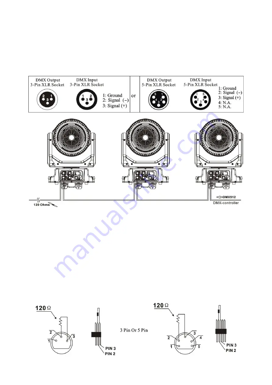
Connect  the  provided  male  side  of  the  XLR  cable  to  the  female  XLR  output  of  your  controller 
and  the  female  side  of  the  XLR  cable  to  the  male  XLR  input  of  the  device

You  can  connect 

multiple  devices  together  in  a  serial  fashion

The  cable  needed  should  be  two  core

screened 

cable with XLR input and output connectors

Please refer to the diagram below

.


Address 53                                    Address 27                                    Address 1 


7.


DMX-512 CONNECTION WITH DMX TERMINATOR 


For  installations  where  the  DMX  cable  has  to  run  over  a  long  distance  or  is  in  an  electrically 
noisy environment

such as in a discotheque

it is recommended to use a DMX terminator

This 

helps in preventing corruption of the digital control signal caused by electrical noise

The DMX 

terminator is an XLR plug with a 120 Ω resistor connected between pins 2 and 3

which is then 

plugged  into  the  output  (female)  XLR  socket  of  the  last  fixture  in  the  chain

Please  see 

illustrations below

.


Summary of Contents for GLW760 IP

Page 1: ...LED MOVING HEAD USER MANUAL GLW760 IP KEEP THIS MANUAL FOR FUTURE NEEDS ...

Page 2: ...wn safety please read this user manual carefully before installing and operating the device CONTENTS 1 SAFETY INSTRUCTIONS 2 2 FEATURES 3 3 FIXTURE OVERVIEW 7 4 DIMENSIONAL DRAWINGS 8 5 INSTALLATION INSTRUCTIONS 9 6 DMX 512 CONTROL CONNECTION 14 7 DMX 512 CONNECTION WITH DMX TERMINATOR 14 8 DEVICE DMX START ADDRESS SELECTION 15 9 DISPLAY 15 10 DMX PROTOCOL 29 11 ERROR MESSAGES 34 12 CLEANING AND M...

Page 3: ... warranty The dealer and manufacturer will not accept liability for any resulting defects or problems If the device has been exposed to temperature changes due to environmental conditions do not power on immediately The resulting condensation could damage the device Leave the device powered off until it has reached room temperature This device falls under protection class I Therefore it is essenti...

Page 4: ... 2 of this manual Handle the device with care avoid shaking or using force when installing or maintaining the device When choosing the installation location please make sure that the device is not exposed to extreme heat moisture or dust If you use the quick lock cam when rigging the device make sure the quick lock fasteners are located in the quick lock holes correctly and securely Operate the de...

Page 5: ...ning COLORS RGBW color mixing uniform linear and speed can be adjustable FEATURES 3 Control channel modes 26 20 48 channels 2 operations modes DMX 512 Master Slave Active Strobe effect with 1 25 flashes per second and pulse effect Beam angle zoom for 5 45 Dimmer 0 100 full range dimming DISPLAY Advanced and convenient full color LCD touch screen with rechargeable battery Locked automatically after...

Page 6: ...grams available upon selection Upgrades fast and convenient through DMX cable Reset DMX address remote lamp switch reset can all be done by the controller Running time of fixture on display for reference OTHER SPEC Input signal isolation guarantees stable signal transmission without interference Advanced RDM function WHIGHT Net weight 16 8 kg PHOTOMETRIC DATA DMX CHANNEL DATA IMAGE ...

Page 7: ...GLW760 IP User Manual XM1586 V1 1 NR 6 ...

Page 8: ...R 7 3 FIXTURE OVERVIEW 1 Lens 2 Display 3 Mode Esc button 4 Left button 5 ENTER button 6 Down button 7 Right button 8 Up button 9 Pan Lock 10 Handle 11 DMX out 12 DMX in 13 RJ45 out 14 RJ45 in 15 Fuse 16 Service Port 17 Valve 18 Power in ...

Page 9: ...GLW760 IP User Manual XM1586 V1 1 NR 8 4 DIMENSIONAL DRAWINGS ...

Page 10: ...light sensor see below picture in blue frame 5 2 INSTALLING OR REPLACING THE PAN MOTOR AND BELT Procedures Step 1 Remove the bottom seal plate Step 2 Remove universal axis Step 3 Release the screws removing the Pan Pulley then can remove the pan belt see below picture in blue frame Step 4 Remove the display screen assembly Step 5 Remove the control board assembly Step 6 Remove the pan motor assemb...

Page 11: ...T MOTOR AND BELT Procedures Step 1 Remove the front head cover assembly Step 2 Remove the lens cover assy Step 3 Remove the motor bracket assembly Step 4 Remove the tilt motor bracket assembly then can replace and install the tilt motor and belt see below picture in blue frame ...

Page 12: ... when rigging de rigging or maintaining the device All electrical connections should be approved by a qualified electrician prior to using the product When the device is permanently installed these installations have to be approved by a qualified person once a year Overhead rigging requires extensive experience including but not limited to calculating working load limits specifying installation ri...

Page 13: ...eners of the first Omega holder into the respective holes on the bottom of the device Tighten the quick lock fasteners fully clockwise Install the second Omega holder Pull the safety cable through the holes on the bottom of the base and over the trussing system or another suitable rigging point Insert the end into the carabiner and tighten the safety screw Important This step is very important to ...

Page 14: ...a safety measure to prevent accidental damage and or injury in the event the clamp fails Important Overhead rigging requires extensive experience including but not limited to calculating working load limits specifying installation rigging materials and periodic safety inspection of all installation material as well as the device If you lack these qualifications do not attempt the rigging of this d...

Page 15: ...Please refer to the diagram below Address 53 Address 27 Address 1 7 DMX 512 CONNECTION WITH DMX TERMINATOR For installations where the DMX cable has to run over a long distance or is in an electrically noisy environment such as in a discotheque it is recommended to use a DMX terminator This helps in preventing corruption of the digital control signal caused by electrical noise The DMX terminator i...

Page 16: ...ol channels of the unit That means changing the settings of one channel will affect only the selected device In the case of the LED moving head which is a 26 channel fixture you should set the starting address of the first unit to 1 the second unit to 27 26 1 the third unit to 53 26 27 and so on 9 DISPLAY The Display offers several features you can set the starting address run the pre programmed p...

Page 17: ... V1 0 0 2U01 V1 0 0 Software version Error Info Error Record 1 Error Record 2 Error Record 10 PAN PAN PAN Personality Status Settings Address Via DMX No DMX Status Pan Reverse Tilt Reverse Pan Degree Feedback LED Degree Change Hibernation ON OFF Close Hold Auto ON OFF ON OFF 630 540 ON OFF 0 180 OFF 01M 99M 15M Add via DMX Auto run if no DMX Pan Reverse movement Tilt Reverse movement Pan Degree Se...

Page 18: ...p Calibration Calibrate Password Pan XXX Password 050 Calibrate and adjust the effects to standard right position Users Mode Set User Mode Basic Mode Standard Mode Extended Mode User Mode A User Mode B User Mode C User s mode to change channel numbers Edit User Mode A Edit User Mode B Edit User Mode C Max Channel XX PAN CH01 Edit User Mode A B C Edit Program Select Programs Auto Pro Part 1 Program...

Page 19: ...ss MODE ESC to return to the main menu 9 1 3 Slave Mode With this function you can define the device as slave 1 Access the main menu 2 Tap the Up Down button until Slave Mode is displayed 3 Press ENTER the display will show Slave Mode 4 Tap the Up Down button the display will show Slave1 Slave2 Slave3 5 Press ENTER to confirm or press MODE ESC to return to the main menu 9 1 4 Auto Program With thi...

Page 20: ...Down the display will show Total Run Time 3 Press ENTER the display will show Total Run Time 4 The display will show XXXX Hours 5 Press ENTER to confirm or press MODE ESC to return to the main menu Last Run Time With this function you can display last the running time of the device The display shows XXXX XXXX stands for the number of hours 1 Tap MODE ESC button access the main menu Tap the Up Down...

Page 21: ...il Temperature Info is displayed Press ENTER the display will show Temperature Info 2 Press Up Down the display will show Head Temp 3 Press ENTER the display will show Head Temp 4 The display show XXX C F 5 Press ENTER to confirm or press MODE ESC to return to the main menu 9 2 3 Ethernet IP 1 Tap MODE ESC button access the main menu Tap the Up Down button until Information is displayed Press ENTE...

Page 22: ...ill show Status settings 2 Press Up Down the display will show Address via DMX 3 Press ENTER the display will show Address via DMX 4 The display show ON Press Up Down the display will show OFF 5 Press ENTER to confirm or press MODE ESC to return to the main menu No DMX Status With this function when the drive is not DMX signal it runs automatism close hold and music the default is hold 1 Tap MODE ...

Page 23: ... show Status settings 2 Press Up Down the display will show Pan Degree 3 Press ENTER the display will show Pan Degree 4 The display show 540 Press Up Down the display will show 630 5 Press ENTER to confirm or press MODE ESC to return to the main menu Feedback With this function you can feedback switch of pan movement or tilt movement 1 Tap MODE ESC button access the main menu Tap the Up Down butto...

Page 24: ...ice Setting Press ENTER the display will show Service Setting 2 Press Up Down the display will show Clear Err Info 3 Press ENTER he display will show Clear Err Info 4 The display show OFF Press Up Down the display will show ON 5 Press ENTER to confirm or press MODE ESC to return to the main menu DFLT Pow E FLY On 1 Tap MODE ESC button access the main menu Tap the Up Down button until Personality i...

Page 25: ...isplay show OFF Press Up Down the display will show ON OFF 5 Press ENTER to confirm or press MODE ESC to return to the main menu Key Lock With this function you can activate the automatic key lock function If this function is activated the keys will be locked automatically after exiting the edit mode for 15 seconds keeping press the MODE ESC key for 3seconds if you do not need this function 1 Tap ...

Page 26: ...n menu Tap the Up Down button until Personality is displayed Press ENTER the display will show Personality 2 Press Up Down the display will show Ethernet IP 3 Press ENTER the display will show Ethernet IP 4 The display show XXX XXX XXX XXX 5 Press ENTER to confirm or press MODE ESC to return to the main menu 9 3 9 Ether Mask IP 1 Tap MODE ESC button access the main menu Tap the Up Down button unti...

Page 27: ...o confirm or press MODE ESC to return to the main menu 9 3 14 Gamma 1 Tap MODE ESC button access the main menu Tap the Up Down button until Personality is displayed Press ENTER the display will show Personality 2 Press Up Down the display will show Gamma 3 Press ENTER the display will show Gamma 4 The display shows 2 2 Press Up Down the display will show 2 0 2 2 2 4 2 6 2 8 5 Press ENTER to confir...

Page 28: ...ntil Effect Adjust is displayed Press ENTER the display will show Effect Adjust 2 Press Up Down the display will show Manual control 3 Press ENTER the display will show Manual control 4 The display show PAN XXX 5 Press ENTER to confirm or press MODE ESC to return to the main menu 9 5 3 Calibration With this function you can calibrate and adjust the effect wheels to their correct positions The pass...

Page 29: ... Down button until Edit grogram is displayed 3 Press ENTER the display will show Edit grogram 4 The display show Select programs Press Up Down the display will show Edit Program Edit Scenes Rec Controller 5 Press ENTER to confirm or press MODE ESC to return to the main menu Run the auto program A master fixture can output to three different program signals to the slave fixture to operate It means ...

Page 30: ...sume Program 2 includes scene of 10 11 12 13 Program 4 includes scene of 8 9 10 Program 6 includes scene of 12 13 14 15 Then it will run as below Example 9 8 Language Set With this function you can set the device language to English or Chinese the default is English 1 Tap MODE ESC button access the main menu 2 Press Up Down the display will show Language Set 3 Press ENTER the display will show Lan...

Page 31: ...n rotation from fast to slow 55 2RPM 0 92RPM 190 193 No rotation 194 255 Backwards Pan rotation from slow to fast 0 92RPM 55 2RPM 7 5 7 Tilt Motor continuous rotation 0 0 127 No function 128 189 Forwards Tilt rotation from fast to slow 65 75RPM 1 0 9RPM 190 193 No rotation 194 255 Backwards Tilt rotation from slow to fast 1 09RPM 65 75RPM 8 6 8 Shutter strobe 32 0 31 Led trun off 32 63 Led turn on...

Page 32: ... 255 Blue 0 Black 255 100 Blue 17 Blue LED Fine all arrays 0 0 255 Fine control for Blue adjustment 18 13 White LED all arrays 0 0 255 White 0 Black 255 100 White 19 White LED Fine all arrays 0 0 255 Fine control for White adjustment 20 14 14 Color Macro 0 0 7 No function 8 39 From RED to YELLOW 40 71 From YELLOW to GREEN 72 103 From GREEN to CYAN 104 135 From CYAN to BLUE 136 167 From BLUE to MAG...

Page 33: ... 99 Reset Others 100 119 Internal program 1 secne1 8 of EEPROM 120 139 Internal program 2 secne9 16 of EEPROM 140 159 Internal program 3 secne17 24 of EEPROM 160 179 Internal program 4 secne25 32 of EEPROM 180 199 Internal program 5 secne33 40 of EEPROM 200 219 Internal program 6 secne41 48 of EEPROM 220 239 Internal program 7 secne49 56 of EEPROM 240 255 No function 21 Red LED array 1 0 0 255 Red...

Page 34: ...een LED array 3 0 0 255 Green 0 Black 255 100 Green 31 Blue LED array 3 0 0 255 Blue 0 Black 255 100 Blue 32 White LED array 3 0 0 255 White 0 Black 255 100 White 45 Red LED array 7 0 0 255 White 0 Black 255 100 White 46 Green LED array 7 0 0 255 White 0 Black 255 100 White 47 Blue LED array 7 0 0 255 White 0 Black 255 100 White 48 White LED array 7 0 0 255 White 0 Black 255 100 White ...

Page 35: ...t is not located in the default position after the reset TILT movement Er TILT head movement error This message will appear after the reset of the fixture if the head s magnetic indexing circuit malfunctions Optical Sensor or Magnetic Sensor fails or the stepper motor is defective or its driving IC on the main PCB The TILT movement is not located in the default position after the reset Zoom wheel ...

Page 36: ...tacts are in good condition This will prevent poor circuit contacts and the resultant overheating We recommend frequent cleaning of the device Please use a moist lint free cloth Never use alcohol or solvents Please refer to the instructions under Installation instructions Should you need any spare parts please order genuine parts from your local dealer 13 SERVICE For all service needs please conta...

Reviews: