LED MOVING HEAD
USER MANUAL
G6H NOVA
KEEP THIS MANUAL FOR FUTURE NEEDS
Page 1: ...LED MOVING HEAD USER MANUAL G6H NOVA KEEP THIS MANUAL FOR FUTURE NEEDS ...
Page 2: ...wn safety please read this user manual carefully before installing and operating the device CONTENTS 1 SAFETY INSTRUCTIONS 2 2 FEATURES 4 3 FIXTURE OVERVIEW 7 4 DIMENSIONAL DRAWINGS 8 5 INSTALLATION INSTRUCTIONS 9 6 DMX 512 CONTROL CONNECTION 13 7 DMX 512 CONNECTION WITH DMX TERMINATOR 13 8 DEVICE DMX START ADDRESS SELECTION 14 9 DISPLAY 14 10 DMX PROTOCOL 30 11 ERROR MESSAGES 36 12 CLEANING AND M...
Page 3: ... CAUTION KEEP THIS DEVICE AWAY FROM RAIN AND MOISTURE Important Damage caused by the disregard of this user manual is not subject to warranty The dealer and manufacturer will not accept liability for any resulting defects or problems If the device has been exposed to temperature changes due to environmental conditions do not power on immediately The resulting condensation could damage the device L...
Page 4: ...wed to be operated within the maximum alternating current as stated in the technical specifications in section 2 of this manual Handle the device with care avoid shaking or using force when installing or maintaining the device When choosing the installation location please make sure that the device is not exposed to extreme heat moisture or dust If you use the quick lock cam when rigging the devic...
Page 5: ...nel modes 20 34 channels 2 operations modes DMX 512 Master Slave mode Strobe effect with 1 25 flashes per second and pulse effect Rotating Prism 16 prism and 5 line prism Macros Beam angle zoom for 1 9 19 in Beam zoom for 2 6 27 in Spot zoom for 3 6 25 in Wash Motorized focus Dimmer 0 100 full range dimming Stepless frost 0 100 linear change frost IP rating IP20 DISPLAY Advanced and convenient col...
Page 6: ...G6H NOVA User Manual XM1557 V1 1 NR 5 OTHER SPEC Input signal isolation guarantees stable signal transmission without interference Advanced RDM function WHIGHT Net weight 23 75 kg PHOTOMETRIC DATA ...
Page 7: ...G6H NOVA User Manual XM1557 V1 1 NR 6 DMX CHANNEL DATA IMAGE ...
Page 8: ... 7 3 FIXTURE OVERVIEW 1 Lens 2 Display 3 Mode Esc button 4 Left button 5 Down button 6 Enter button 7 Right button 8 Up button 9 Pan Lock 10 Handle 11 Tilt Lock 12 RJ45 in 13 Power out 14 RJ45 out 15 DMX out 16 Power in 17 DMX in 18 Fuse ...
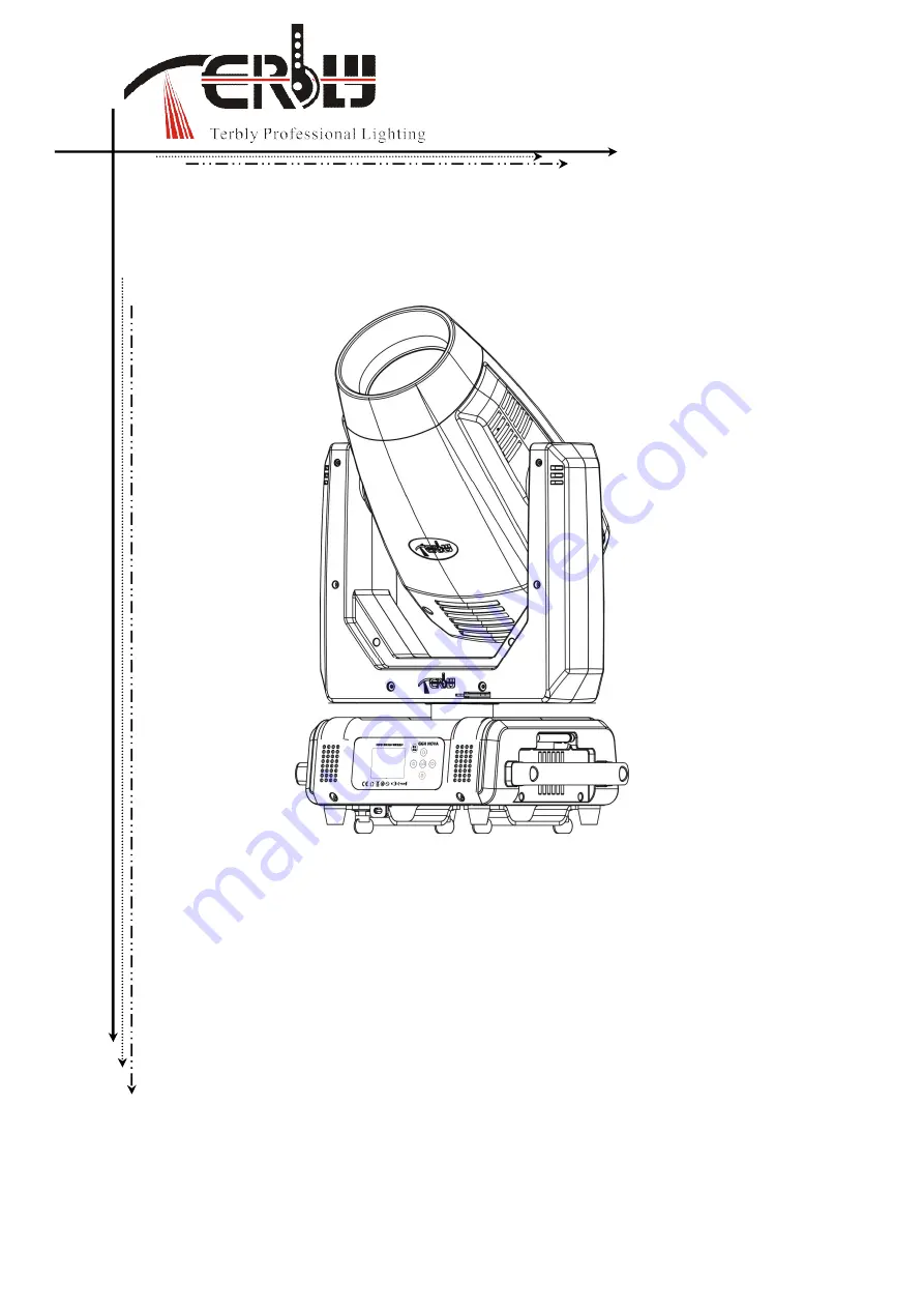
Page 9: ...G6H NOVA User Manual XM1557 V1 1 NR 8 4 DIMENSIONAL DRAWINGS ...
Page 10: ...ed Always use a gloves or a cloth to handle the lamps during insertion and removal Do not install lamps with a higher wattage They generate higher temperatures than which the device was designed for WARNING THE BULB SHOULD BE REPLACED WHEN DAMAGED OR HEAT DISTORTION CAUTION DISCONNECT THE FIXTURE FROM POWER AND ALLOW IT TO COOL FOR TEN MIN Procedures 1 Please put the fixture on a smooth desk relea...
Page 11: ...ALIFIED PERSON The structure on which the device is rigged must be able to support 10 times the weight of the device for 1 hour without any critical deformation occurring The installation must always be secured with a secondary safety attachment e g the included appropriate safety cable Never stand directly below the device when rigging de rigging or maintaining the device All electrical connectio...
Page 12: ...ners of the first Omega holder into the respective holes on the bottom of the device Tighten the quick lock fasteners fully clockwise Install the second Omega holder Pull the safety cable through the holes on the bottom of the base and over the trussing system or another suitable rigging point Insert the end into the carabiner and tighten the safety screw Important This step is very important to e...
Page 13: ... safety measure to prevent accidental damage and or injury in the event the clamp fails Important Overhead rigging requires extensive experience including but not limited to calculating working load limits specifying installation rigging materials and periodic safety inspection of all installation material as well as the device If you lack these qualifications do not attempt the rigging of this de...
Page 14: ...Please refer to the diagram below Address 1 Address 25 Address 49 7 DMX 512 CONNECTION WITH DMX TERMINATOR For installations where the DMX cable has to run over a long distance or is in an electrically noisy environment such as in a discotheque it is recommended to use a DMX terminator This helps in preventing corruption of the digital control signal caused by electrical noise The DMX terminator i...
Page 15: ...rol channels of the unit That means changing the settings of one channel will affect only the selected device In the case of the moving head which is a 24 channel fixture you should set the starting address of the first unit to 1 the second unit to 25 24 1 the third unit to 49 24 25 and so on 9 DISPLAY The Display offers several features you can set the starting address run the pre programmed prog...
Page 16: ... Temperature Info Head Temperature XXX Temperature in the head Ethernet IP Ethernet IP XXX XXX XXX XXX XXX XXX XXX XXX IP Information Fan Info 1U_FAN1 Encode Info PAN ENCODE TILT ENCODE Encode Info Software Version V1 X X Software version Lamp Control Lamp On Off Automatic On Lamp On via DMX Lamp Off via DMX Lamp Power Mode ON OFF ON OFF ON OFF ON OFF 190W 240W 280W Lamp on off Lamp on off Power o...
Page 17: ...Manual Control PAN XXX Fine adjustment of the lamp Calibration Calibrate Password Pan XXX Password 050 Calbrate and adjust the effects to standard right position Users Mode Set User Mode Basic Mode Standard Mode Extended Mode User Mode A User Mode B User Mode C User s mode to change channel numbers Edit User Mode A B C Max Channel XX PAN CH01 Preset User modes A B C Edit Program Select Program Aut...
Page 18: ...s MODE ESC to return to the main menu 9 1 3 Slave Mode With this function you can define the device as slave 1 Access the main menu 2 Tap the Up Down button until Slave Mode is displayed 3 Press ENTER the display will show Slave Mode 4 Tap the Up Down button the display will show Slave1 Slave2 Slave3 5 Press ENTER to confirm or press MODE ESC to return to the main menu 9 1 4 Auto Program With this...
Page 19: ...tion 2 Press Up Down the display will show Total Run Time 3 Press ENTER the display will show Total Run Time 4 The display will show XXXX Hours 5 Press ENTER to confirm or press MODE ESC to return to the main menu Last Run Time With this function you can display last the running time of the device The display shows XXXX XXXX stands for the number of hours 1 Tap MODE ESC button access the main menu...
Page 20: ...splay will show Time Information 2 Press Up Down the display will show LastRun Password 3 Press ENTER the display will show LastRun Password The time password is 038 4 Press ENTER to confirm or press MODE ESC to return to the main menu Clear Last Run With this function you can clear last run time of the fixture The display shows ON or OFF Press Enter to confirm 1 Tap MODE ESC button access the mai...
Page 21: ...own button until Information is displayed Press ENTER the display will show Information Tap the Up Down button until Temperature Info is displayed Press ENTER the display will show Temperature Info 2 Press Up Down the display will show Head Temp 3 Press ENTER the display will show Head Temp 4 The display show XXX C F 5 Press ENTER to confirm or press MODE ESC to return to the main menu 9 2 3 Ether...
Page 22: ...t be striked even the menu Lamp is turned to ON as the lamp switch is compelled to turned off When the temperature unit after the temperature value come to lowercase letter c or f it means menu Lamp is turned to ON but the lamp is not full dimming up When the temperature unit after the temperature value come to capital letter C or F it menu Lamp is turned to ON and the lamp is full intensity 9 3 1...
Page 23: ... DMX With this function you can select if you can switch the lamp off via an external controller DMX channel of internal programs value 224 239 Select ON by turning the encoder if you wish to enable this function or OFF if you don t 1 Tap MODE ESC button access the main menu Tap the Up Down button until Lamp Control is displayed Press ENTER the display will show Lamp Control 2 Tap the Up Down butt...
Page 24: ...ER to confirm or press MODE ESC to return to the main menu Pan Reverse With this function you can reverse the Pan movement 1 Tap MODE ESC button access the main menu Tap the Up Down button until Personality is displayed Press ENTER the display will show Personality Tap the Up Down button until the display will show Status settings Press ENTER the display will show Status settings 2 Press Up Down t...
Page 25: ...ture stay without DMX signal for 15 mins Factory default And the fixture will be reset before working once it receive DMX signal again 1 Tap MODE ESC button access the main menu Tap the Up Down button until Personality is displayed Press ENTER the display will show Personality Tap the Up Down button until the display will show Status settings Press ENTER the display will show Status settings 2 Pre...
Page 26: ...s keeping press the MODE ESC key for 3seconds if you do not need this function 1 Tap MODE ESC button access the main menu Tap the Up Down button until Personality is displayed Press ENTER the display will show Personality Tap the Up Down button until the display will show Display Setting Press ENTER the display will show Display Setting 2 Press Up Down the display will show Key Lock 3 Press ENTER ...
Page 27: ...nu 9 4 8 Ether Mask IP 1 Tap MODE ESC button access the main menu Tap the Up Down button until Personality is displayed Press ENTER the display will show Personality 2 Press Up Down the display will show Ethernet Mask IP 3 Press ENTER the display will show Ethernet Mask IP 4 The display show XXX XXX XXX XXX 5 Press ENTER to confirm or press MODE ESC to return to the main menu 9 4 9 Set Universe 1 ...
Page 28: ...R to confirm or press MODE ESC to return to the main menu 9 6 2 Manual Control When set to Manual Mode fixture will be back to factory settings If want to adjust brightness can adjust by shutter and dimming channel channel value is 0 255 Other functions can be set according to user s real need 1 Tap MODE ESC button access the main menu Tap the Up Down button until Effect Adjust is displayed Press ...
Page 29: ...MODE ESC button access the main menu 2 Tap the Up Down button until Users mode set is displayed 3 Press ENTER the display will show Users mode set 4 The display show Edit User Mode A first channel Press Up Down the display will show Edit User Mode B Edit User Mode C 5 Press ENTER to confirm or press MODE ESC to return to the main menu 9 8 EDIT PROGRAM 1 Tap MODE ESC button access the main menu 2 T...
Page 30: ...ditor of the scene there are as many as 250 scenario editors and every scene can have a program connection of 10 Note Part 2 Part 3 repeat in accordance with the Part1 s repeat For example When Part 1 uses Program 2 Part 2 uses Program 4 Part 3 uses Program 6 Assume Program 2 includes scene of 10 11 12 13 Program 4 includes scene of 8 9 10 Program 6 includes scene of 12 13 14 15 Then it will run a...
Page 31: ...ction 4 6 6 Shutter strobe 0 31 Shutter closed 32 63 No function shutter open 64 95 Strobe effect slow to fast 96 127 No function shutter open 128 159 Pulse effect in sequences 160 191 No function shutter open 192 223 Random strobe effect slow to fast 224 255 No function shutter open 5 7 7 Dimmer intensity 0 255 Intensity 0 to 100 8 Fine Dimmer intensity 0 255 Dimmer intensity fine 6 8 9 0 255 Zoo...
Page 32: ...OR 92 100 CTB 101 109 UV 110 118 CTO 119 127 BLUE 128 189 Clock wise scroll from fast to slow 190 193 No rotation 194 255 Counter clock wise scroll from slow to fast 16 Color Wheel Fine 0 255 Color Wheel color change to any position Fine 11 13 17 Cyan Color 0 255 Cyan 0 white 255 100 Cyan 18 Cyan Color Fine 0 255 Cyan Fine 12 14 19 Magenta Color 0 255 Magenta 0 white 255 100 magenta 20 Magenta Col...
Page 33: ...o18 176 183 Macro19 184 191 Macro20 192 199 Macro21 200 207 Macro22 208 215 Macro23 216 223 Macro24 224 231 Macro25 232 239 Macro26 240 247 Macro27 248 255 Random CMY 15 17 24 Speed Of CMY Colour macro Speed 0 255 Speed Max Min 16 18 25 Rotating gobos cont rotation 0 10 Beam open 11 21 Spot open 22 31 Rot gobo 1 32 41 Rot gobo 2 42 51 Rot gobo 3 52 61 Rot gobo 4 62 71 Rot gobo 5 72 81 Rot gobo 6 8...
Page 34: ... indexing 0 9 hole 18 20 28 10 17 Gobo 1 18 25 Gobo 2 26 33 Gobo 3 34 41 Gobo 4 42 49 Gobo 5 50 57 Gobo 6 58 65 Gobo 7 66 73 Gobo 8 74 81 Gobo 9 82 89 Gobo 10 90 97 Gobo 11 98 105 Gobo 12 106 112 Gobo 1 shake slow to fast 113 119 Gobo 2 shake slow to fast 120 126 Gobo 3 shake slow to fast 127 133 Gobo 4 shake slow to fast 134 140 Gobo 5 shake slow to fast 141 147 Gobo 6 shake slow to fast 148 154 ...
Page 35: ...o 12 224 231 Macro 13 232 239 Macro 14 240 247 Macro 15 248 255 Macro 16 20 22 31 Rotating 16 Line prism 0 127 Prism indexing 128 189 Clock wise rotation from fast to slow 190 193 No rotation 194 255 Counter clock wise rotation from slow to fast 32 Rotating 16 Line prism indexing Fine 0 255 Fine indexing 21 23 33 Frost 0 127 Disable frost 128 255 Enable frost 22 24 34 Lamp on off reset internal pr...
Page 36: ... 93 Reset Gobos 94 96 Reset Shutter 97 99 Reset Others 100 119 Internal program 1 120 139 Internal program 2 140 159 Internal program 3 160 179 Internal program 4 180 199 Internal program 5 200 219 Internal program 6 220 239 Internal program 7 240 255 No fuction ...
Page 37: ...he head s magnetic indexing circuit malfunctions Optical Sensor or Magnetic Sensor fails or the stepper motor is defective or its driving IC on the main PCB The TILT movement is not located in the default position after the reset CMY wheel Er CMY wheel error This message will appear after the reset of the fixture if the head s magnetic indexing circuit malfunctions sensor failed or magnet missing ...
Page 38: ...stepper motor is defective or its driving IC on the main PCB The Prism_R 1 movement is not located in the default position after the reset Prism 16 wheel Er Prism 16 wheel error This message will appear after the reset of the fixture if the head s magnetic indexing circuit malfunctions sensor failed or magnet missing or the stepper motor is defective or its driving IC on the main PCB The Prism 16 ...
Page 39: ...d loss of output due to accumulation of dust dirt on the lens 2 Clean the fans each week to ensure maximum airflow and efficient thermal cooling This will ensure the light source is operated in the best possible condition 3 A detailed electrical check by an approved electrician every quarter to make sure that the circuit contacts are in good condition This will prevent poor circuit contacts and th...
Page 40: ......