NEED MORE HELP?
Support: http://support.teradek.com
→
Contains tips, information and all the latest firmware & software updates.
TERADEK SUPPORT STAFF:
support
@
teradek.com or call 888
−
941
−
2111 ext2 (Mon
−
Fri 7am to 6pm PST)
PAIRING INSTRUCTIONS
Bolt DSMC2 is a zero delay
wireless video transmission
system designed to fit seamlessly
onto the back of
RED DSMC2
cameras. Bolt transmits 1080p60
4:2:2 video at up to 500/1000/3000
ft line of sight over the unlicensed
5GHz band with less than 1ms
latency.
Confirm that
PLEASE ACTIVATE PAIRING ON TX
is displayed on receiver’s OLED
display
(O)
or the monitor.
Using the
Menu joystick
, select
OK
to finish pairing. This process takes up to a
minute. If pairing fails, power cycle the receiver and the transmitter and try again.
On the transmitter, use a
paper clip (or similar)
to press the
Reset/Pairing
button
(C)
. After a few seconds,
Pairing: XXXXX...
should be displayed on the
receiver’s OLED display or the monitor. If not, power cycle the receiver and the
transmitter, then try again.
Using the
Menu joystick
(N)
on the receiver, navigate through the menus and
select
Pairing
.
2
4
5
3
E
K
B
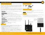
Teradek regularly releases new firmware versions to improve performance, add new features, or to fix vulnerabilities.
Visit https://www.teradek.com to update your device with the latest firmware.
ZERO DELAY
WIRELESS
HD VIDEO
CONNECT AND POWER
Move the power switch
(I)
to the
ON
position.
C
1
Turn on the Bolt transmitter and receiver. If the Bolt receiver does not have an OLED
display, connect a monitor to the receiver’s video output.
Place Bolt firmly against the back of the DSMC2 camera.
2
To remove Bolt, loosen the four captive screws and pull it off the back of the camera.
Tighten the four captive screws in a cross pattern ("X" pattern) using a 2.5mm hex wrench.
DO NOT
OVER
-
TIGHTEN.
3
The
Power status
LED
(E)
will indicate power is present if a battery is connected to the DSMC2 Battery
Module or if power is provided via the DSMC2 camera. The camera will boot when the camera’s power
button is pressed. While the camera is booting, Bolt will also boot.
5
6
If using a DSMC2 Battery Module, place it firmly against the back of Bolt. Make sure the connector
in the front of the battery module aligns with the connector on the back of Bolt.
4
1
NOTE: If the
Power status LED is on, but the camera does not boot, remove Bolt then re
-
attach, making
sure it’s properly seated. Always use an X pattern when tightening the M4 screws.
D
F
G
H
I
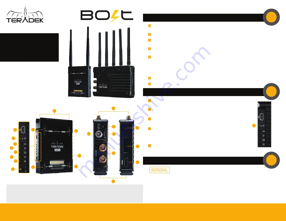
Bolt TX
Bolt RX
A:
RP-SMA connectors
B:
Mini USB port
C:
Reset/Pairing button
D:
Wireless On/Off LED
E:
Power status LED
F:
Video status LED
G:
Network status LED
H:
Fault/Error
I:
Power switch
J:
Captive screws
K:
HDMI output
(opposite side)
L:
Power input
M:
3G-SDI output
N:
Menu joystick
O:
OLED display
P:
HDMI output
Q:
NATO rail mount
Bolt 3000 XT -RX
FOR DSMC2
L
I
B
A
M
Q
C
P
O
N
A
J
Bolt TX
J
J
J
DEVICE OPERATION
GENERAL
•
Keep the transmitter and the receiver at close range for 60 seconds after powering on the devices. This
allows them to scan for and select the best wireless channel.
•
For best results when using multiple Bolt systems in the same area, place the transmitters and receivers
a few feet apart from each other.
•
Operation of other wireless equipment may interfere with Bolt. For best results, separate other
wireless transmitters and receivers as much as possible.
Remove the protective MOD GUARD plate from the front of the Bolt DSMC2 by unscrewing
the four captive screws from the back
(J)
.
7
Bolt DSMC2 - TX


